Advertisement
Quick Links
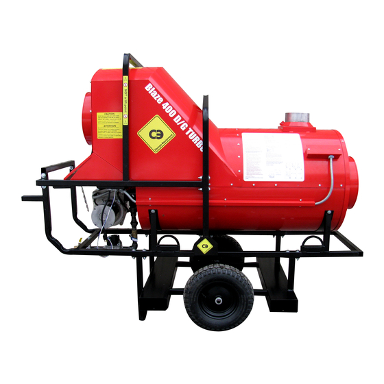
EB400G
Field Assist Troubleshooting Guide
Welcome
to the Campo "Field Assist Troubleshooting Guides".
These guides were developed to assist the working technicians in the field. We've supplied issues
and solutions to the most common problems encountered in the field. If you need assistance while
troubleshooting on the job, they are easy to store in your smart phone, tablet or computer.
Getting Started is easy! Just click on
'Page #'
for the problem you are encountering
Burner control is locked-out on reset
Burner control is NOT locked-out on reset
Page 2
Page 15
➢ Tech Tips
and
Bulletins
for
you...Page 31 +
➢ Quick set-up and Installation Guides
and Tools of the Trade for
you...Page 33 +
➢ Contact
1
Us...Page 30
HOME
Advertisement

Related Manuals for Campo Equipment Blaze EB400G


Summary of Contents for Campo Equipment Blaze EB400G
- Page 1 EB400G Field Assist Troubleshooting Guide Welcome to the Campo “Field Assist Troubleshooting Guides”. These guides were developed to assist the working technicians in the field. We’ve supplied issues and solutions to the most common problems encountered in the field. If you need assistance while troubleshooting on the job, they are easy to store in your smart phone, tablet or computer.
- Page 2 Burner is locked out on reset • Before resetting the burner control, ensure you have between 7-14” WC pressure supplied to the gas valve. • Ensure the ‘switchover valve’ is in the proper position for LP OR NG • You reset the control and it goes through the 60 second purge, but doesn’t ignite……...
- Page 3 You reset the control and it goes through the 60 second purge, but doesn’t ignite… • Install your manometer in the outlet port of the gas valve. • Reset the burner control. • After the 60 second purge, check to see if gas pressure is coming through the valve.
- Page 4 If gas pressure is present… ✓Defective igniter ✓Defective ignition cable ✓Broken electrode ➢ Test the components... Page 5 HOME...
- Page 5 Testing the Igniter SHUT OFF the gas supply to the burner before testing! Inspect the ignition electrode for cracks. Inspect the ignition cable for cracks. Inspect the electrode gap, ensuring the gap is 1/8”. • With the gun still outside the burner casing, re-connect the ignition cable to the igniter.
- Page 6 If gas pressure is NOT present… ✓ON/OFF switch is in the OFF position ✓Defective 24v Transformer ✓Defective Burner Control ✓Defective gas valve ➢ Test the components…Page 7 HOME...
- Page 7 Checking the ON/OFF switch • Ensure the ‘switchover valve’ is in the proper position for LP OR NG • Ensure the gas valve switch is in the ON position. ➢ Continue to… Page 8 HOME...
- Page 8 Checking the 24 volt transformer Check black and red stripe wires on 6 prong plug For 24 volts ✓ If 24 volts is NOT present, the transformer is defective. • If 24 volts is present… Page 9 HOME...
- Page 9 Checking the burner control and gas valve Reset the Burner Control. After the 60 second purge, check for 24 volts on the white and violet wires on the 6 prong plug. ✓ If 24 volts is present, after the 60 second purge, the gas valve is defective.
- Page 10 You reset the burner control. The burner motor does not start and the burner control locks out on reset. ✔ Defective burner motor. ✔ Defective Burner Control ✔ Defective Motor Relay Light Flashing reset control ➢ Test the components…Page 11 HOME...
- Page 11 Checking burner motor, motor relay and burner control Reset burner control, then check for 120 volts on burner motor relay coil. ✓ If 120 volts is NOT present, defective burner control ✓ If 120 volts is present, defective burner motor relay OR burner motor ➢...
- Page 12 Checking burner motor and motor relay (continued) Reset the burner control and check for 120 volts going to the burner motor. ✓ If 120 volts is present, defective burner motor ✓ If 120 volts is NOT present, defective burner motor relay HOME...
- Page 13 You reset the burner control, but the reset light is solid red during the purge, and the control locks out on reset ✓ The air proving switch is defective ✓ The air hose is cracked or busted ➢ Note: The air proven switch contact must be open to start and close after the burner motor starts.
- Page 14 You reset the burner control and after the pre-purge, the burner fires up, but the flame goes out after 5 or 10 seconds. • Clean or replace flame rod and wire. ✔ The flame rod is defective or dirty ✔ Flame rod lead wire is defective ➢...
- Page 15 The Burner is NOT locked out on reset • If the Burner Control is NOT locked out on Reset and will not start… Page 16 • If the Circulating Fan Fails To start… Page 23 • If the fan is starting intermittently, erratically or inconsistently…Page 24 •...
- Page 16 If the Burner Control is NOT locked out on Reset and will not start… Check for 120 volts between Terminal (L1) and Common (L2) on the burner control. • If 120 volts is present… Page 17 • If 120 volts is NOT present…Page 19 HOME...
- Page 17 If 120 volts is PRESENT on burner control… ✓ Defective Bypass Switch Jump TR-TW ✓ Defective Burner Control ➢ Test the components... Page 18 HOME...
- Page 18 Testing the bypass switch and burner control To check the bypass switch, place a jumper wire on terminals TR-TW Jump TR-TW ✓ If the burner starts, the bypass switch is defective Terminals TR-TW ✓ If the burner does not start, the burner control is defective HOME...
- Page 19 If 120 volts is NOT present on burner control between L1 and (L2) ✓ Defective Thermal Limit Disc 150⁰F ✓ Defective Thermocouple ✓ Defective Temperature Controller ✓ Defective Fan Motor Thermostat Switch Thermocouple Thermal Limit Disc Thermostat Thermostat Temperature Controller Switch Inside Fan Switch Sealed Motor...
- Page 20 Testing the temperature controller ➢ NOTE: If the display on the temperature controller is reading 000 (or other false reading), the thermocouple Is defective. Check for 120 volts on the orange wire terminal on the temperature controller. ✓ If 120 volts is NOT present, the temperature controller is defective.
- Page 21 Test the high limit 150ºF disc and motor thermostat Test for 120 volts on each terminal of the disc to ground. ✓ If 120 volts is NOT present, the fan motor temperature switch is defective. ✓ If 120 volts is present on only 1 terminal of the disc, the disc is defective.
- Page 22 Checking the fan motor thermostat ➢ NOTE: On late model, Blaze construction heaters, the circulating fan motors are equipped with a thermal heat thermostat that is not serviceable. ➢ The motor thermostat is wired in series with the 120-volt limit and temperature controller circuit.
- Page 23 If the circulating fan fails to start… With the Fan Override switch in the ON position, check for 120 volts on the fan relay (R1) on the fan motor terminal. (Blue wire) ✓ If there is 120 volts, the circulating fan motor is defective.
- Page 24 If the fan is starting intermittently, erratically or inconsistently… The EB400D is equipped with redundant controls to ensure positive starts for the circulating blower fan. ✓ If the temperature controller display reaches 90ºF and the fan does not start, the controller is defective. ✓...
- Page 25 Circulating fan does not shut off First, ensure that the ambient temperature at the 110ºF fan disc is less than 80ºF. ✓ The Fan Override switch is in the ON position. (Turn it to the OFF position) ✓ Defective 110ºF fan disc ✓...
- Page 26 Circulating fan does not shut off Checking – 110ºF fan disc Check for 120 volts between ground and each terminal. Note: If 120 volts is present on BOTH terminals, the disc is defective. If 120 volts is present on ONE terminal only, the disc is GOOD…Page 35 HOME...
- Page 27 Circulating fan does not shut off Checking - circulating fan relay Check for 120 volts on the relay coil terminals. ✓ 0 volts indicates a defective relay • If 120 volts is present on the relay coil… Page 36 HOME...
- Page 28 Circulating fan does not shut off Checking - temperature controller and thermocouple If the circulating fan 110⁰F disc is good AND there is 120 volts on the circulating fan relay (R1) coil. ✓ Defective temperature controller ✓ Defective Thermocouple ➢ Testing the components… Page 37 HOME...
- Page 29 Circulating fan does not shut off Checking - temperature controller and thermocouple Testing the thermocouple… 1. Remove the (small) red and white thermocouple wires from the back of the temperature controller 2. Install a jumper wire between the two terminals thermocouple ✓...
- Page 30 We pride ourselves in offering… The best technical support in the industry …Here To Help! sales@campoequipment.com 1-866-323-0042 HOME...
- Page 31 Tech Tips And Bulletins and more for You… Don't get left behind. Stay on the top of your game and become a… “ Campo Field Assist Program Member”. ➢ As a member you will receive updates and notifications of any changes to the Guides. ➢...
- Page 32 Tech Tips And Bulletins and more for You… ➢ Replacing the thermocouple made easier…Page (Not Available yet) ➢ Using a Combustion Analyser…Page 38 ➢ Replacing circulating fan motor…Page (Not Available yet) HOME...
- Page 33 EB400G Installation Guide ➢ Start-up procedure…Page 34 ➢ Adjusting proper gas pressures…Page (not available Yet) ➢ Electrical hook up…Page (not available Yet) ➢ Gas Piping…Page (not available Yet) ➢ Venting the heater…Page 39 ➢ Adjusting the burner combustion…Page 38 ➢ Gas train test ports and adjustment locations…Page 42 HOME...
- Page 34 Start-up procedure gas fired units. • All heaters should be set up by a qualified gas technician. • Make sure all piping and fittings are tight and free from gas leaks. • Purge all air from gas lines connected to the regulator. •...
- Page 35 Help us Help you! Instruments for heater set-up and diagnostics. What you need to commission the heater! Combustion Analyzer Voltmeter Manometer ➢ Start-up continued…Page 36 HOME...
- Page 36 Start-up procedure gas continued. Have a qualified gas fitter determine the correct regulators to use and the correct diameter hose to feed the unit with fuel according to pressure in the supply line and length of lines. Gas fitters have charts to help them determine this information. •...
- Page 37 Start-up procedure gas continued. With the switch for the burner in the off position, plug in the heater, turn the fan manual override switch to ON position and ensure voltage remains steady. Return fan manual override switch to OFF position. •...
- Page 38 Adjusting the burner for clean and reliable combustion With the use of a combustion analyzer. • Adjust the o2 levels between 3% and 4%. • To archive this…. open or close the air adjustment on the burner…Page 41 ➢Note: Opening the air adjustments will increase the o2 levels and closing the air adjustments will decrease the o2 levels.
- Page 39 Venting outside a building. • Make sure to install a stack minimum 36” on the flue. • Make sure to install a rain cap on the flue pipe. • Make sure that flue gases are not being circulated into by the cooling fan and pushed into the space you are heating.
- Page 40 Best practices for venting when heater is located inside a building • Avoid using as many 90-degree elbows as possible • Venting runs should be as short as possible 36” • Vertical rise minimum 3 feet, 5 feet is better outside the building. •...
- Page 41 Combustion and adjusting the air settings. Proper air adjustments must be preformed for reliable combustion • Recommended air settings are indicated in manufactures instructions as: Example: first number being the shutter second number being the band. ➢ Note: recommend air settings are approximate and will change with altitude and fuel oil temperature.
- Page 42 Gas Train Blaze 600/700/1000 NOTE: Gas Train for the EB200G and EB400G… page 44 Pressure regulator adjustment under cap Switch over valve inlet pressure port Outlet pressure port Gas solenoid valve test port HOME...
- Page 43 Using a Combustion Analyzer While the flue-stack is cold, pre-drill a 1/4” hole in the flue- stack 18” above the heater flue collar. • Turn on the burner and let it run for 5 minutes. • Insert your combustion analyzer probe into the flue stack hole. •...
- Page 44 Gas Train – EB200G and EB400G Switchover valve for LP OR NG Test outlet port Gas valve On/Off Switch Test Inlet port HOME...
Need help?
Do you have a question about the Blaze EB400G and is the answer not in the manual?
Questions and answers