Advertisement
Quick Links
Advertisement

Related Manuals for Victor 4106

Summary of Contents for Victor 4106
- Page 1 Victor 4106 earth resistance tester 2, 3, 4 poles method - 1 -...
-
Page 2: Section One Introduction
Section One Introduction Warning Read this Manual carefully before use the Instrument. Generalization The instrument is a multifunctional earth resistance/earth resistivity tester equipped with a microcomputer. The instrument employs digital signal settlement technology, which can draw earth measurement signals, possess features of high frequency, high accuracy and high resistance, and measure earth resistance/ earth resistivity accurately. - Page 3 ⚫ Measurement Function for series interference voltage. ⚫ Backlight Function to view the test results in dimly areas. ⚫ Setting Function to release the residual resistance (Rk) on the test leads. ⚫ Setting Function for auxiliary earth spike interval under earth resistivity measurement, setting range: 1m~30m. ⚫...
- Page 4 IEC61557-5 safety requirements. This Manual contains warnings and safety rules which have to be observed by the user to ensure safe operation of the instrument and to maintain it in safe condition .Therefore, read through these operating instructions before using the instrument. The mark indicated on the instrument, means that the user must refer to the related parts in the manual for safe operation of the instrument.
- Page 5 ⚫ Never attempt to make any measurement if any abnormal conditions, such as a broken cover or exposed metal parts are present on the Instrument and Test Leads. ⚫ Replace Test Leads with new one in same specification and same electrical specification when it is broken.
- Page 6 Section Two Specification Safety and conformity Overload Protection E-S, E-H terminals: AC250V/10 seconds IEC61010-1(CAT Ⅲ 600V, POLUTION degreeⅡ) IE C61010-2-032 (special requirements for hand- held current Probes) Legal Conformity IEC61557-1, 5(electronic safety requirement voltage distribution system below AC 1000V and DC 1500V conforms to IEC61326-1,Group 1, Class B conforms to EC61326-1,...
- Page 7 Indoor, outdoor operation(no waterproof),at an altitude of 0~2,000 Ambient Condition for Operation meter Stored Data 100 groups Indicator for Over-range Battery Type eight AA 1.5V Alkaline (LR6) batteries Low Battery displays battery mark Automatic Power-off The default value is 5 minutes if no operation which is adjustable. Closed –...
- Page 8 Series interference voltage (UST) Measuring Range Resolution Frequency Range Accuracy 0.0V~20.0V 45~200Hz Sine 0.1V 2%+5 ⚫ Output Resistance about 32V. ⚫ Measuring speed: twice every second. ⚫ Max. overload: 250Vrms. Measurement for residual resistance of Test Leads (Rk) This function can be activated in 20Ω position. Range: 0.00Ω~5.00Ω. RK value saved in 20Ω...
- Page 9 ⚫ Use probes conforming to IEC61557-5 when measuring current and voltage. ⚫ Open-circuit voltage Um: Max. About 50Vpp, rectangle wave. ⚫ Short-circuit current lm: Max.20mA, but Im☓(RH +RE)< Um ⚫ Measuring frequency : 94Hz, 105Hz, 111Hz, 128Hz, manual selection. ⚫ Measuring time: Typical 12 seconds.
- Page 10 200Ω·m~1999Ω·m 2000Ω·m 1Ω·m 2.00kΩ·m~19.99kΩ·m 20kΩ·m 0.01kΩ·m 20.0kΩ·m~199.9kΩ·m 200KΩ·m 0.1kΩ·m 200kΩ·m~3768kΩ·m 2000kΩ·m 1kΩ·m ⚫ All technical data are valid listed in earth resistance. ⚫ Interval between earth spikes : a=1.0m~30.0m. The maximum operation error within the measurement range should not exceed ±30% of the measured basic value, which is shown in the following table.
- Page 11 temperature 0ºC and 35ºC 4.2 in Section 1 Series interference See 4.2 and 4.3 4.2 and 4.3 in Section 5 voltage Resistance of auxiliary earth 4kΩ+100 RE but ≤ 50kΩ 4.3 in Section 5 electrode and probe 2 +E 2 +E 2 +E Operation error 4.3 in Section 5...
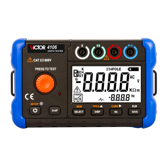
- Page 12 Section Three Instrument layout Instrument body Figure 1 - 12 -...
- Page 13 Terminal Figure 2 Terminals Function Illustration H(C) H terminals (C terminals ) - blue S(P) S terminal ( P terminal )- red ES terminal - green E terminal - black Display Unit The Notes and Warnings for the Instrument operation are displayed in all kinds of marks and information. Here is the detailed illustration for Marks and Information.
- Page 14 Figure 4 Mark, Information Illustration Recall/delete saving data Main screen 234POLE Earth resistance testing methods: 2POLE, 3POLE, 4POLE AC voltage compare - 14 -...
- Page 15 Low battery mark Fail / Pass Unit in the Main Display Screen voltage : V Resistance unit: Ω(ohm), kΩ(thousand ohms ) Resistance rate unit: Ω·m(ohm·meter), kΩ·m(thousand ohms· meter) Auxiliary screen Noise mark : display when UST≥5V RH is higher than limits RS is higher than limits Both RH and RS are higher than limits Select Yellow Key function...
- Page 16 Press key 图 3 Figure 3 Press Key Illustration Power-on or turning on the backlight. Press for less than 2 seconds to turn on or off the backlights; press for more than 2 seconds to power off. - 16 -...
- Page 17 Press to select testing functions: 4 Pole, 3 Pole, 2 Pole, earth resistivity (ρ); Default Mode: 4 -Pole method. Under earth resistance measurement / earth resistivity measurement function. Press to select displayed data in Main Display Screen: Under 4 Pole mode: RE→RH→RS→UST→RK→RE, default display RE; Under 3 Pole mode: RE→RH→RS→UST→RK→RE, default display RE;...
- Page 18 Press to select ' Yellow Key' function, the Screen displays in the left corner. Yellow Key functions are illustrated in the following part. Enter into/ exit from the Instrument Setting function Recall/ exit from data in the saving part alter testing frequency: 128Hz→111Hz→105Hz→94Hz→128Hz, default value: 128Hz. Use the power adapter Open the soft rubber door on the side of the instrument,and insert the special power adapter of the instrument into the power socket (the instrument must be turned off when inserting or pulling out the special power adapter;...
- Page 19 Section Four Preparation for testing Power-on To turn on the Instrument, press key to connect with the power. To turn off the Instrument, press key for more than 2 seconds to cut the power. When being powered-on, the Instrument starts inner-self diagnose and displays power-on mark firstly, and then undertakes relevant operations.
- Page 20 Low battery display Mark displays in the upper-left Main Screen after power-on means low battery, please replace with new ones (recharge if the batteries are chargeable)and then use. Warning To avoid electrical shock hazard or personnel injury due to wrong readings, replace the batteries as soon as possible if the LED displays mark;...
- Page 21 Figure 5 Step four: press TEST Key to measure Rk; Step five: press Key to save Rk value, and the Main Screen displays SAVE mark in the lower-left part. Note: the Rk value will be saved in the Instrument after powering off. The residual resistance value is valid in all resistance range;...
- Page 22 Figure 6 Figure 7 To clean the saved Rk value, press Key for more than 2 seconds in Rk compensation interface, and the ”mark, repress to clean the Rk compensation value. Main Screen displays ' Figure 8 Rk value is ' 0.00Ω' after cleaning. Step six: press key to exit from Rk compensation interface.
- Page 23 Series interference voltage testing function This measurement function detects the possible interference voltage and its frequency Before undertaking earth resistance measurement, the function is automatically activated in every testing method. If exceeding the preset limit value which indicates over-high interference voltage, the measurement will be automatically prohibited When Ust≥20V, the testing result interface displays ' ' warning, and prohibits measurement.
- Page 24 The function of comparison test is only valid for grounding resistance test of 2-pole method and 3-pole method and 4-pole method. Press the key to start the comparison function,and the symbol will be displayed on the screen after the comparison function is started. Press the key again to turn off the comparison function.
- Page 25 (1) Press key to select measurement method: 3 Pole (the Main Screen displays 3POLE in the upper part); (2) Press key to select measurement frequency (display in auxiliary display part) (3) Residual resistance of Rk ① Firmly insert each plug of 3 test leads (black, red, blue) to the corresponding terminals E,S and H on the instrument respectively.
- Page 26 5-10m 5-10m Figure 9 (6) Pres Key to save measurement results (see section six ' saving and reading of the measurement s results”) Note ⚫ The readings may not correct when the auxiliary earth resistance is too high. Stick the Auxiliary Earth Spikes S and H in the moist part of the soil.
- Page 27 failure of correct measurement due to high value of earth resistance compared with auxiliary earth resistance. Danger The measurement cannot be made when a warning message appears on the Main Screen. Voltages more than 20V exist between the instrument terminals. Precise measurement (4 POLE) The' ES' Terminal is also used with the other terminals used at the 3-pole Precise measurements.
- Page 28 (4) Connection of Auxiliary Earth Spikes and Test Leads(See figure 10) Stick the Auxiliary Earth Spikes S and H into the ground deeply which should be aligned from the earthed equipment under test. Connect the black Test Lead to the earthed equipment under test, the red Test Lead to the Auxiliary Earth Spike S and the blue Test Lead to the Auxiliary Earth Spike H in sequence.
- Page 29 Press Key to read RH, RS, UST and RK values. (6) Press Key to save measurement results (see section six ' saving and reading of the measurement results ' ) Notes ⚫ The readings may not correct when the auxiliary earth resistance is too high. Stick the Auxiliary Earth Spikes S and H in the moist part of the soil.
- Page 30 Terminals to be used: E and H Terminals Test Leads: E and H Terminals respectively Auxiliary Earth Spike: None is used (1) Press key to select measurement method: 2-Pole (the Main Screen displays 2POLE in the upper part); (2) Press key to select measurement frequency (display in auxiliary display part);...
- Page 31 Figure 11 Note ⚫ The results in simplified measurement include auxiliary earth resistance. Thus, the displayed value may cause error if the auxiliary earth resistance is over high. ⚫ The measurement result may be incorrect if interference voltage is higher than 5V, and the noise mark ' ' displays.
- Page 32 ρ=2aR ρ:mean value of earth resistivity ( · m). a:intervals between earth spikes (m). R:measured resistance() Terminals to be used: E, ES, S, H Terminals Test Leads: connect to the E, ES, S, H Terminals. Auxiliary Earth Spike: 4 pcs Measurement method is shown as follows: (1)...
- Page 33 Figure (4) Setting for the Auxiliary Earth Spike See ' Instrument Settings' for detailed settings. (5) Press TEST key to restart measurement. The Main Screen displays ' - - - -' message. The measured earth resistivity value and related information are displayed on the Main Screen when the measurement is finished.
- Page 34 failure of correct measurement due to high value of earth resistance compared with auxiliary earth resistance. Danger The measurement cannot be made when a warning message appear on the Main Screen. Voltages more than 20V exist between the instrument terminals. Section Six Store/recall the measurement results The instrument can store xx measurement results.
- Page 35 ⚫ Data cannot be saved while the Low Battery Mark is displayed on the Main Screen. ⚫ When the saved data reaches to the max limit of the capacity, Full' is displayed on the auxiliary part of the Main Screen and no more data can be saved. How to recall the saved data The saved data can be read on the Main Screen according to following sequence.
-
Page 36: Section Seven Instrument Setting
(1) Remove the Test Leads. (2) Press key to enter into MEM function. When the Main Screen displays in the upper left part, the Instrument will read the last record in default setting. (3) Press key, the Main Screen displays mark to enquire whether to delete data or not. - Page 37 When selecting the last item, repress key to exit setting mode. Default Setting Items Function Value Setting range is 0 ~ 90 minutes,press key to select blinking auto-power-off minutes position ,press key to set flicker digits; Setting as 0 indicates canceling auto- power- off function.
- Page 38 This section provides some basic maintenance procedures. Repair, calibration, and servicing not covered in this manual must be performed by qualified personnel. For maintenance procedures not described in this manual, contact a Victor’s Service Center. General maintenance Periodically wipe the case with a damp cloth and detergent; do not use abrasives or solvents.
- Page 39 Clean the terminals as follows: (1) Turn the Meter off and remove all test leads. (2) Shake out any dirt that may be in terminals. (3) Soak a new swab with alcohol. Clean each terminal with the swab. Replacing the batteries The Meter is powered by eight AA batteries (IEC LR6).
- Page 40 Thus, the earth resistance can be calculated by: Meas And it is irrelevant with auxiliary earth electrode resistance RH. The Generator runs in frequency between 70-140Hz. It should keep intervals for less than 5Hz with 16 , 50 or 60Hz and some standard frequency of their harmonic. Principle of Earth Resistivity (ρ) Measurements Earth resistivity indicates the geology and physical quantity of the calculated and designed earthed system.