Advertisement
Quick Links
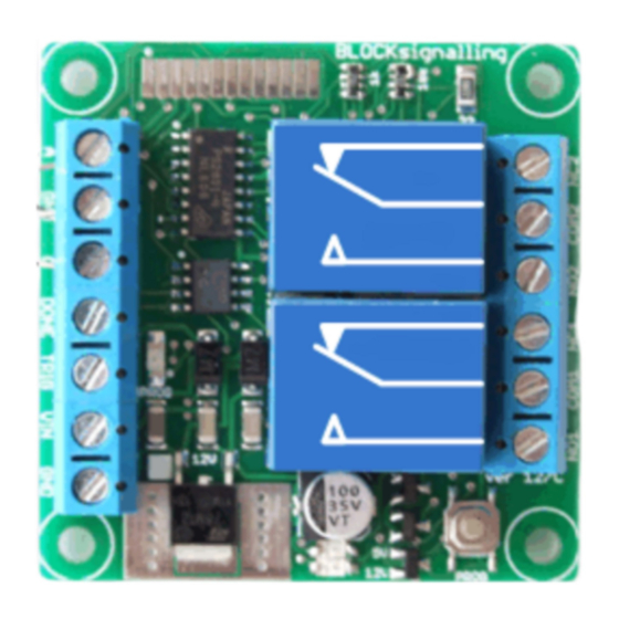
UNIVERSAL MODULE FOR SEQUENTIAL OPERATIONS M1
Pre-programmed multi-functional module with two separate relay outputs
Capable for driving points motors, operating signals, switching and reversing
loco direction, etc
Action is triggered by push-button, switch, reed-relay, or another module of
the same type
Action is carried out until the train is detected by the infra-red sensor or the
module times out
When the action is completed, the module provides an output signal which
can be connected to other modules of the same type
Programs can be easily adjusted to give great flexibility in operation
Advertisement

Related Manuals for BLOCKsignalling M1

Summary of Contents for BLOCKsignalling M1
- Page 1 UNIVERSAL MODULE FOR SEQUENTIAL OPERATIONS M1 Pre-programmed multi-functional module with two separate relay outputs Capable for driving points motors, operating signals, switching and reversing loco direction, etc Action is triggered by push-button, switch, reed-relay, or another module of ...
- Page 2 Introduction The BLOCKsignalling module M1 has been designed to carry out a pre-programmed function when it is triggered, such as powering a section of track to move a train forward. It then it waits until a train reaches the infra-red sensor. At this point, the module completes the action (eg stops the train) and signals on one of its outputs that the task has been completed (the "DONE"...
- Page 3 BLOCKsignalling www.blocksignalling.co.uk Connections The module has screw terminals for all its external connections. The train sensor connects to the A, GND, and C terminals. The DONE and TRIG terminals are for connection to adjacent modules. The TRIG input is activated when connected to GND, by a switch, push button or other module.
- Page 4 BLOCKsignalling www.blocksignalling.co.uk Connecting the Infra-Red Sensor An Infra-Red source and Infra-Red detector are moulded into a single 5mm x 6.5mm package that can be located below the track bed to reflect light off rolling stock. Identify the Sensor 1 leads from the diagrams (there is a small chamfer on the edge of the casing) and connect to the terminals marked A and C on the module.
- Page 5 BLOCKsignalling www.blocksignalling.co.uk Programming Many of the settings used by the module can be changed (re-programmed) by the user. The main memory location is memory 2 (m2) which is used to select which program the module runs (Program 1, Program 2, etc).
- Page 6 BLOCKsignalling www.blocksignalling.co.uk Program 1 - Test Program This is the default program when the module is first supplied and is designed to test the correct operation of the module. The timings cannot be adjusted. Connect up the sensor (see later) and a 12V DC power supply. The led and push button are optional.
- Page 7 BLOCKsignalling www.blocksignalling.co.uk The led flashing shows the module is searching for a train and the module will now wait for an object in front of the sensor. Place you hand close to the sensor and after 5 seconds Relay 2 will turn on for five seconds then off after a further 5 seconds, followed by Relay 1 turning off five seconds later.
- Page 8 BLOCKsignalling www.blocksignalling.co.uk Program 2 - Fiddle Yard A fiddle yard has a queue of trains. When the one at the front of the queue departs each of the trains behind move up one position in the queue. In the drawing below, we are just showing one train, which is stationary at location A (due to the module not powering the isolated section of track).
- Page 9 In the diagram below, we have left out the power supply connections to the M1 modules for clarity. We have also left out the push button, because you can press the push button on the first module and it has the same effect.
- Page 10 BLOCKsignalling www.blocksignalling.co.uk Page 10 of 29...
- Page 11 BLOCKsignalling www.blocksignalling.co.uk Program 3 - Points Operation This program is intended to operate sets of points (using solenoid points motors) to route trains. Once triggered, Relay 2 is energised and selects the route direction, then Relay 1 is energised for 1 second to operate the points.
- Page 12 BLOCKsignalling www.blocksignalling.co.uk Wire the normal and reverse wires of the points to suite the direction you want the points to operate. Page 12 of 29...
- Page 13 BLOCKsignalling www.blocksignalling.co.uk Program 4 - Wiring Tortoise or Cobalt Points Motors This program is designed to operate stall type points motors. Once triggered, both relays operate to reverse the polarity of the feed to the points motor. When the train reaches the sensor, both relays are de-energised and the feed to the points motors is restored to the previous polarity.
- Page 14 BLOCKsignalling www.blocksignalling.co.uk Page 14 of 29...
- Page 15 BLOCKsignalling www.blocksignalling.co.uk Program 5 - Change Direction This program is designed to change the direction of the traction current. Before triggering, both relays are de-energised and the power passes straight through. Once triggered, the traction current direction is reversed. When the train reaches the sensor, the traction current is restored to the original direction.
- Page 16 BLOCKsignalling www.blocksignalling.co.uk Program 6 - Dapol Signal This program is designed to operate a Dapol Signals. Once triggered, Relay 2 is operated for 1 second to change the signal. After a delay, Relay 1 is operated for 1 second to change the signal.
- Page 17 BLOCKsignalling www.blocksignalling.co.uk Program 7 - Led or Bulb Signal (3-aspect) This program is designed to operate a Led or Filament Bulb Signals. When the power is switched on, with the signals wired as below, the green aspect will show. Once the module is triggered, the signal will immediately switch to red, then yellow after a delay.
- Page 18 BLOCKsignalling www.blocksignalling.co.uk Programs 8 – Universal program The following program allows you to design you own uses for the module and gives full flexibility to change the operation of the module. There are many settings to adjust the timing of the pulses, set the number of pulses, change which action triggers the module, ability to set the delays to be randomised and so on.
-
Page 19: Introduction To Programming
Introduction to Programming This section of the document covers program 8, an additional program added to the M1 module which allows the user to set their own timings for the operations of the relays on the module. To fully understand this section, I recommend reading through once lightly, then concentrating on the examples at the end. -
Page 20: Programming Options
BLOCKsignalling www.blocksignalling.co.uk Programming Options As well as the option to change all the timings as given in the diagram above, it is also possible to: Select whether a pulse occurs after the trigger input or not. Select whether a pulse occurs after the IR input or not. - Page 21 BLOCKsignalling www.blocksignalling.co.uk Changing the Triggering In all the above diagrams, the first trigger for the module is the TRIG input. It is possible to change the first trigger to be the TRIG input, or the IR sensor, or by grounding the C terminal or to have no trigger required.
- Page 22 BLOCKsignalling www.blocksignalling.co.uk Extra Delays It is possible to add extra delays after triggering has occurred (either from the TRIG input or following an IR trigger). It is also possible to add a delay after all the relay operations are completed, before the DONE output signal is sent (see next section).
- Page 23 BLOCKsignalling www.blocksignalling.co.uk Delaying the DONE signal It is possible to add an additional delay after all the relay operations are completed, before the DONE output signal is sent. The setting for this is m16. The DONE pulse occurs after the following: Both relays are de-energised, and the value of m16 has elapsed (measured from the second trigger).
-
Page 24: Programming Example
The settings are as follows: Set m1 to 1 (perform Factory Reset, so we know all the settings are at their default value) Set m2 to 8 (to select program 8) Set m4 to 2 (sets Relay 1 to mode 2, ie one pulse resulting from the TRIG input, and one pulse... -
Page 25: Factory Reset
BLOCKsignalling www.blocksignalling.co.uk Program Flow Diagram As mentioned above, there are a number of memory location which can programmed with different values to change the operation of the module. Before starting, it is a good idea to write down the memory locations and the values you are going to set them to. - Page 26 BLOCKsignalling www.blocksignalling.co.uk Memory Default Value Possible Values Comment Factory Reset Test Program Fiddle Yard Points Tortoise or Cobalt Points Change Direction Dapol Signal Led or bulb signal Universal Program 1 to 10 Number of IR samples to detect train 1 to 10...
- Page 27 BLOCKsignalling www.blocksignalling.co.uk Altering the Timings of the Inbuilt Programs The following diagrams show the settings for the timings of the inbuilt-programs. Refer to the table above for the default values. The timings of the Default Program cannot be changed. In the Points Program, the pulse output of Relay 1 is always 1 second.
- Page 28 BLOCKsignalling www.blocksignalling.co.uk In the Dapol Program, the pulse output of Relay 1 and Relay 2 is always 1 second. The colour of the aspect lit is shown in the background of the timing diagram for program 7. Here is a reminder of the memories used for the Universal Program.
- Page 29 BLOCKsignalling www.blocksignalling.co.uk Suggested Test Setup Once you have programmed all your settings, it is recommended to test the operation of the module to check that it operates as expected. The diagram below shows a push button connected to the TRIG input, to ground that input when pressed.
Need help?
Do you have a question about the M1 and is the answer not in the manual?
Questions and answers