
Related Manuals for PreSens Microx 4


Summary of Contents for PreSens Microx 4
- Page 1 Microx 4 & Microx 4 trace TRANSMITTERS Fiber optic oxygen transmitters Instruction Manual...
- Page 3 Microx 4 & Microx 4 trace Specification: Fiber optic oxygen transmitters for use with non-invasive oxygen sensors, sensor probes & oxygen microsensors Software: PreSens Datamanager Document filename: IM_MX4-MX4trace_dv3 All rights reserved. No parts of this work may be reproduced in any form or by any means - graphic, electronic, or mechanical, including photocopying, recording, taping, or information storage and retrieval systems - without the written permission of the publisher.
-
Page 5: Table Of Contents
Table of Contents Preface ........................... 8 Safety Notes ........................9 Description of the Microx 4 & Microx 4 trace Transmitter ........10 Scope of Delivery ....................... 11 Top Panel ........................12 Bottom Panel ......................12 Control Panel ......................13 Barcode Reader ......................14 Installation ........................ - Page 6 Barcode Reader ......................71 6.4.1 Specifications ......................71 6.4.2 Safety Instructions ..................... 72 Pt100 Configuration ....................72 Maintenance ........................ 77 Service ......................... 77 CE and FCC Conformity .................... 78 Concluding Remarks ....................79 © 2016 PreSens Precision Sensing GmbH www.PreSens...
-
Page 8: Preface
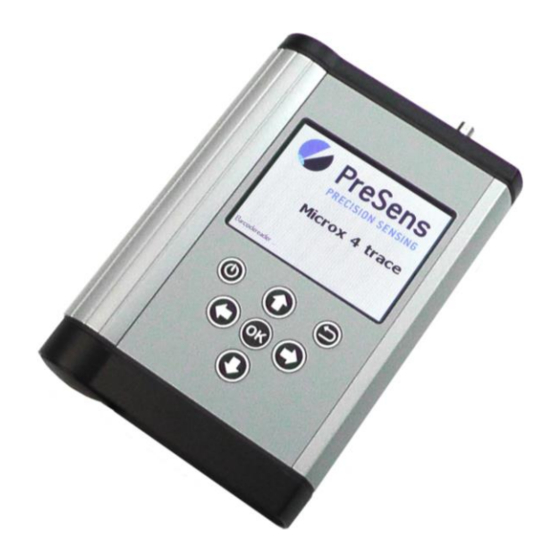
The Microx 4 & Microx 4 trace are compact, portable, completely stand-alone fiber optic oxygen transmitters. The data management and export is PC supported. The Microx 4 & Microx 4 trace are developed especially for small fiber optic oxygen sensors, oxygen microsensors, flow-through cells and non-invasive sensors. They are based on a novel technology, which creates very stable, internally referenced measured values. -
Page 9: Safety Notes
PreSens is explicitly not liable for direct or indirect losses caused by the application of these measurement systems. In particular it has to be considered that malfunctions can occur due to the naturally limited lifetime of the sensor depending on the respective application. -
Page 10: Description Of The Microx 4 & Microx 4 Trace Transmitter
3 Description of the Microx 4 & Microx 4 trace Transmitter The Microx 4 & Microx 4 trace are precise single channel fiber optic oxygen transmitters with temperature compensation, and additional compensation of pressure and salinity. They can be used with small fiber optic oxygen sensors as well as microsensors. The Microx 4 is designed for small fiber optic oxygen sensors with sensor type PSt7-10 and oxygen microsensors type PSt7-02 (limit of detection 0.03 % oxygen, 15 ppb dissolved oxygen). -
Page 11: Scope Of Delivery
Sensor handling & calibration via barcode 3.1 Scope of Delivery Fig. 2 Case with all delivered equipment Microx 4 OR Microx 4 trace, fiber optic oxygen transmitter with protection kit PreSens Datamanager software (CD) USB cable USB-Power adapter (5 VDC, min. 1 A) with different connector pieces... -
Page 12: Top Panel
Description of the Microx 4 & Microx 4 trace Microx 4 & Microx 4 trace 3.2 Top Panel The top panel is equipped with a connector for the fiber optic sensor, a connector for the temperature sensor, and the barcode reader. -
Page 13: Control Panel
Fig. 5 Control panel of the Microx 4 & Microx 4 trace The Microx 4 & Microx 4 trace are completely stand-alone devices. The LCD display and the buttons allow operating the transmitter without connection to a PC / notebook. In the lower part of the display the functions of the buttons in the respective menu, submenu or window are shown. -
Page 14: Barcode Reader
3.5 Barcode Reader Fig. 6 Scanning a sensor barcode The integrated barcode reader on the top panel of the Microx 4 & Microx 4 trace facilitates sensor handling and management. The barcode reader can be activated in different menus or submenus. -
Page 15: Installation
4 Installation 4.1 Set-up Fig. 7 Set-up for Microx 4 & Microx 4 trace. Top: Stand-alone use with sensor spot; middle: Stand- alone use with needle-type microsensor; bottom: PC controlled use with the extended software, e. g. parallel control of 3 transmitters. - Page 16 Remove the protective cap from the male plug on the polymer optical fiber or the fiber of the microsensor and insert it in the ST connector of the Microx 4 / Microx 4 trace. The ST plug has to be inserted and slightly turned clockwise to fasten it. Be careful not to snap off the optical fiber, especially when connecting a microsensor;...
-
Page 17: Software Installation
Microx 4 & Microx 4 trace 4.2 Software Installation The Microx 4 & Microx 4 trace are delivered with the PreSens Datamanager software, which allows transferring sensor, user and measurement data between the transmitter and a PC / notebook. Furthermore, barcodes can be created with this software. - Page 18 Install. Installing .NET Framework 4 will require a few minutes. Fig. 12 .NET Framework 4 license agreement When PreSens Datamanager installation is completed click the Finish button. Fig. 13 Installation is completed. Click Finish to close the...
-
Page 19: Adjustment Of The Regional Settings Of The Operating System
Installation Microx 4 & Microx 4 trace 4.3 Adjustment of the Regional Settings of the Operating System To change the regional settings on your PC press Start and go to the Control Panel. Choose Regional and Language Options. Fig. 14 Control Panel – Classic View... - Page 20 Installation Microx 4 & Microx 4 trace Fig. 16 Customize Regional Options window – Numbers tab Click Customize again and go to the Date tab now. In the drop down menu Short date format you have to select `dd.MM.yy´ and choose the dot `.´ in Date separator.
-
Page 21: Battery Usage & Charging
15 minutes is the default setting, and can be changed to user requirements. (For Energy Management Settings please refer to chapter 5.6.2.) The Microx 4 & Microx 4 trace comprise rechargeable batteries for self-contained power supply. Rechargeable batteries are subject to normal wear which is more or less pronounced depending on operating and storage conditions. - Page 22 If you want to charge the batteries to 100 %, please connect the Microx 4 / Microx 4 trace to the power supply with the USB-power adapter. Plug the USB cable to the supplied USB-power adapter (5 VDC, min. 1 A) and connect the adapter to the main power grid.
-
Page 23: Operation
Status bar Main screen Navigation bar Fig. 22 Main measurement screen The Microx 4 / Microx 4 trace display is divided into three sections: Status bar: it shows Time: Microx 4 & Microx 4 trace have 24 hour clock settings. - Page 24 Operation Microx 4 & Microx 4 trace User: Next to the user symbol the name of the currently selected user is displayed. Logging: This symbol indicates that logging is activated. This symbol is displayed when logging is not activated. Battery status: The battery symbol on the right indicates the battery status.
-
Page 25: User
Operation Microx 4 & Microx 4 trace 5.2 User Fig. 23 Main menu – User selected User management allows selecting or creating / deleting different users. The user information will be stored with every measurement in the respective measurement file. - Page 26 Operation Microx 4 & Microx 4 trace Pressing the button will switch to a keyboard screen (see Fig. 25). Use the arrow buttons to move on the keyboard and the button to select the respective letter or number. The new User Name will show in the highlighted box at the bottom.
-
Page 27: Sensors
Operation Microx 4 & Microx 4 trace 5.3 Sensors Fig. 26 Main menu – Sensors selected Sensors management shows a list of all sensors you have used with the Microx 4 / Microx 4 trace, the Sensor Name, Sensor Type, and the... -
Page 28: Add A New Sensor
Operation Microx 4 & Microx 4 trace highlighted sensor will be deleted. The currently activated sensor - shown in the status bar - cannot be deleted; you will have to select another sensor first, and then return to deleting the sensor you want removed. -
Page 29: Add A New Sensor Via Barcode
Operation Microx 4 & Microx 4 trace 5.3.1.1 Add a New Sensor via Barcode Please note that you do not necessarily have to go to the Sensors management menu to add a new sensor. If you have the barcode for your new sensor at hand you... -
Page 30: Add A New Sensor Manually
Operation Microx 4 & Microx 4 trace As soon as the barcode with the new sensor data is scanned a keyboard screen opens. Use the arrow buttons to move on the keyboard and the button to select the respective letter or number. - Page 31 Sensor type of your new sensor (Microx 4: PSt7-10 or PSt7-02; Microx 4 trace: PSt7-10, PSt7-02, PSt8-10 or PSt8-02) and type in the Sensor Constants. You can find the sensor constants and calibration data on the Final Inspection Protocol delivered with your oxygen sensor.
-
Page 32: Calibrate Sensors
Operation Microx 4 & Microx 4 trace Fig. 35 Keyboard screen to enter Sensor Name Sensor Name A keyboard screen opens to name the new sensors. Use the arrow buttons to move on the keyboard and the button to select the respective letter or number. The new sensor name will show in the highlighted box at the bottom. -
Page 33: Calibration Via Barcode
It is possible to do a sensor calibration and use the obtained calibration values to generate a barcode with the PreSens Datamanager software (see chapter 5.7.1). This barcode can be applied for calibrating all sensors of the same batch as the one you have calibrated. - Page 34 Operation Microx 4 & Microx 4 trace Fig. 38 Calibration Temperature screen Calibration Temperature T0: Temperature at the first calibration point. Selecting Auto the temperature at the first calibration point will be measured with the Pt100 temperature sensor. Connect the Pt100 temperature sensor to the respective connector on the transmitter´s top panel and make sure it is inserted in the medium of the first calibration...
- Page 35 Microx 4 & Microx 4 trace In the upper main screen the Present Values measured by the Microx 4 / Microx 4 trace are shown. Set the first calibration point Cal0: Place the oxygen sensor (and temperature sensor, if you have chosen...
-
Page 36: Measurement Settings
Operation Microx 4 & Microx 4 trace 5.4 Measurement Settings Fig. 40 Main menu – Measurement Settings selected In the Meas. Settings menu you are able to change general settings for your measurements. If you do not change the measurement settings, the settings of your last measurement will be applied. -
Page 37: Temperature Compensation
Fig. 43 Measurement Settings – Pressure compensation Use the navigation buttons to move to the Pressure box. With Auto selected, the integrated pressure sensor of the Microx 4 / Microx 4 trace will measure the atmospheric pressure and © 2016 PreSens Precision Sensing GmbH ww.PreSens. -
Page 38: Measurement Conditions
Operation Microx 4 & Microx 4 trace these values will be used for pressure compensation. Select Manual, if the atmospheric pressure during measurements is known. Pressure values can be inserted in hPa, mbar, PSI, atm, or torr. Switch to the desired pressure unit and change the pressure value in the input field. -
Page 39: Interval
Operation Microx 4 & Microx 4 trace 5.4.5 Interval Fig. 46 Measurement Settings – select time Interval Use the navigation buttons to move to the Interval box and select the measurement mode. With Single Scan selected one single measurement is taken. Selecting... - Page 40 Operation Microx 4 & Microx 4 trace Fig. 48 Measurement Browser – List of measurement files : Navigate up and down in the measurement file list. : Select the highlighted measurement file. The new measurement data will be added to the existing file.
-
Page 41: Measurement
Operation Microx 4 & Microx 4 trace measurement file list without creating the new file use the button. When you have finished typing the name go to the Done button and press . The new measurement file will show in the file list. - Page 42 Operation Microx 4 & Microx 4 trace starting the measurement. (In manual mode the temperature unit can be changed in the Meas. Settings, see also chapter 5.4.1.) In case you have selected automatic temperature measurement and the temperature sensor is not connected or not working properly the display will show an error message (see Fig.
- Page 43 Operation Microx 4 & Microx 4 trace : Change the Oxygen Unit. Pressing the button changes the oxygen unit on the display and the last measurement value will be shown in the respective oxygen unit immediately. You can choose: For PSt7(-02/-10) sensor in conditions % a.
-
Page 44: Details Screen
Operation Microx 4 & Microx 4 trace 5.5.2 Details Screen Fig. 54 Details measurement screen Details screen gives additional information about measurement and measurement settings. Oxygen: In the Oxygen box the currently or last measured oxygen value is displayed in the selected oxygen unit. -
Page 45: Graph Screen
Operation Microx 4 & Microx 4 trace : Start / Stop the measurement. According to your measurement settings a single scan or interval measurement will be started. Pressing the button again will stop the measurement. : Go back to Simple view. - Page 46 Operation Microx 4 & Microx 4 trace Fig. 56 Pop-up window in graph screen. You cannot change the oxygen unit while the Graph screen is displayed. Switch back to the Simple Details screen to change the oxygen unit. In case your measurement values cannot be calculated in the desired unit and represented in the graph (e.
-
Page 47: Scan A New Sensor
A notification window will open showing the message “Sensor successfully scanned!”. If the sensor has not been used with Microx 4 & Microx 4 trace before and is not yet stored in the sensor list a keyboard screen opens to name the new sensors. -
Page 48: Device Settings
5.6.1 Device Settings Screen Fig. 61 Device Settings screen This menu allows changing general settings of the Microx 4 / Microx 4 trace transmitter. Time Date will be saved with every measurement in the respective measurement file. - Page 49 Time: Set the current time. h = hour m = minute s = second The Microx 4 & Microx 4 trace use 24 hour time settings. Date: Set the current date. d = day m = month y = year...
-
Page 50: Energy Management
5.6.2 Energy Management Fig. 62 Energy Management screen In the Energy Management menu different settings can be changed to save battery power when using the Microx 4 / Microx 4 trace. Use the buttons to navigate between input fields. Press... - Page 51 Operation Microx 4 & Microx 4 trace Long Term Measurement can be used if the measurement interval is set to at least 10 seconds. Logging has to be activated. As soon as measurements are started you will have to confirm activating this function (see Fig.
-
Page 52: About Screen
5.6.3 About Screen Fig. 67 About screen Here the serial number, LED Status, and Firmware Version of your Microx 4 / Microx 4 trace is displayed. In case of any problems with your transmitter please have this information ready when contacting our service team. -
Page 53: Sensor Details Screen
You can see all calibration data as well as the sensor constants. 5.7 Subsequent Data Handling Connect the Microx 4 / Microx 4 trace to an USB port of your PC / notebook with the supplied USB cable. Then start the PreSens Datamanager software. - Page 54 Microx 4 & Microx 4 trace Data stored on the PC (in the chosen working directory) is displayed on the left in the Database box. The data stored on the connected Microx 4 / Microx 4 trace is displayed on the right in the Device box.
-
Page 55: Sensor Data Management
Operation Microx 4 & Microx 4 trace Fig. 71 PreSens Datamanager screen without device connected Go to File (in the menu bar) and choose Exit to close the PreSens Datamanager software. 5.7.1 Sensor Data Management In the Sensors menu new sensors can be added and multiplied, existing sensors deleted, sensor data transferred between PC / notebook and device, and a barcode for a specific sensor can be generated (see Fig. - Page 56 The new sensor will show in the Database box; select the sensor and use the button to transfer sensor data to the Microx 4 / Microx 4 trace. Batch ID Lot Nr Fig. 73 Final Inspection Protocol: Batch ID and Lot Nr Multiply: This function eases adding multiple sensors from the same batch to the sensor list.
- Page 57 Operation Microx 4 & Microx 4 trace Fig. 74 Duplicate the sensor The selected number of sensors will be created, all with a unique Sensor ID and calibration data according to the selected sensor. The new sensors will be named after the selected sensor and numbered continuously.
- Page 58 Operation Microx 4 & Microx 4 trace Fig. 76 Transferring newly created sensors to the Device Delete sensor data: Click on the respective sensor you want deleted so it is highlighted. You can select a sensor from the Database or the Device. Then press the Delete button.
- Page 59 Operation Microx 4 & Microx 4 trace Fig. 77 QR Code window You can also select multiple sensors and press the Barcode button to create several barcodes at once. Fig. 78 Multiple barcodes generated When saving the generated barcodes in image file format (.png, .jpg, .bmp) each newly generated barcode is stored as an individual file (here, e.
- Page 60 Operation Microx 4 & Microx 4 trace Fig. 79 .pdf file of multiple barcodes © 2016 PreSens Precision Sensing GmbH ww.PreSens.
-
Page 61: Measurement Data Management
PC / notebook. Transferring larger measurement files will take some time. The PreSens Datamanager will show a progress bar. You can stop data transfer by pressing the Cancel... - Page 62 Operation Microx 4 & Microx 4 trace Delete a measurement file: Click on the respective measurement file you want deleted so it is highlighted. You can select a measurement file from the Database or the Device. Then press the Delete button.
-
Page 63: User Management
Operation Microx 4 & Microx 4 trace 5.7.3 User Management In the User menu you are able to add a new user or delete an existing user and transfer user data between PC / notebook and the device. Fig. 83 PreSens Datamanager: User tab... -
Page 64: Change The Working Directory
At the bottom of the software screen the Current working directory is shown, in which all the data transferred from the Microx 4 / Microx 4 trace is going to be saved on your PC / notebook. Click on the Change button next to it and choose another directory for data storage in the file browser window that opens. -
Page 65: Error Notification & Troubleshooting
(see chapter 5.7.1), and repeat the scan. Barcode Reader not Barcode reader cannot be Recharge the Microx 4 & Microx 4 ready. Battery too low! operated; there is not trace batteries. enough power left. No Barcode... -
Page 66: Device Menu Structure
Operation Microx 4 & Microx 4 trace 5.9 Device Menu Structure Main Simple Oxygen Measurement Temperature Details Oxygen (+ phase angle, amplitude) Temperature Measurement Name General (measurement settings) Graph Temperature ... -
Page 67: Technical Data
Technical Data Microx 4 & Microx 4 trace 6 Technical Data 6.1 Specifications OPTICAL SENSOR Microx 4 Microx 4 trace Oxygen sensor PSt7-10, PSt7-02 PSt7-10, PSt7-02, PSt8-10, PSt8-02 ST compatible, 200 µm – 1 mm PMMA Fiber Optical connector Channels... - Page 68 Technical Data Microx 4 & Microx 4 trace POWER SUPPLY 4 AA Nickel-metal hydride cells (min. 2200 mAh) Use only AC adapter (5 VDC / min. 1 A) supplied for recharging. Supply voltage 5 VDC Current / Power max. 900 mA / max. 4.5 W...
-
Page 69: Operational Notes
6.2 USB-Power Adapter Microx 4 & Microx 4 trace always have to be used with the original USB-power adapter (5 VDC, min. 1 A) which is supplied. 6.3 Rechargeable Batteries 6.3.1 Changing the Batteries... - Page 70 Operational Notes Microx 4 & Microx 4 trace Fig. 86 Open battery compartment and battery pack; remove the battery connector. Take out the battery pack as far as the connection wires allow; then remove the battery connector. Now you are able to remove the battery pack. You can exchange the 4 AA rechargeable batteries.
-
Page 71: Safety Instructions
Operational Notes Microx 4 & Microx 4 trace 6.3.2 Safety Instructions Caution: To avoid the risk of personal injury or property damage from fire or electrical shock, only use the specified batteries. Do not remove the batteries from the device to charge them. Use the AC power adapter (5 VDC, min. -
Page 72: Safety Instructions
Class II laser product 6.5 Pt100 Configuration For using the Microx 4 / Microx 4 trace with another temperature sensor than the one that can be provided by PreSens, a fitting connector has to be attached to the desired temperature sensor. - Page 73 Operational Notes Microx 4 & Microx 4 trace Pin-out Connector housing: cable shielding Insert with solder contacts Pin 1: cable shielding Pin 2: I- Pin 3: V+ Pin 4: V- Pin 5: I + Fig. 88 All connector parts Prepare your temperature sensor and all connector parts: ©...
- Page 74 Operational Notes Microx 4 & Microx 4 trace Put the bend relief, clamping nut, and collet chuck over the cable of your temperature sensor. Fig. 89 Strip the wire; preferably tin the strands. Fig. 90 Solder the wires to the insert contacts according to pin-out.
- Page 75 Operational Notes Microx 4 & Microx 4 trace Attach the half-shells to the insert. Fig. 93 Fig. 94 Fig. 95 Cut the shielding and push the collet chuck toward the half-shells, so the shielding is entrapped between half-shells and collet chuck.
- Page 76 Fig. 98 Push the bend relief over the clamping nut and you have finished attaching the connector to your temperature sensor. Now it can be used with the Microx 4 / Microx 4 trace. Fig. 99 © 2016 PreSens Precision Sensing GmbH...
-
Page 77: Maintenance
Operational Notes Microx 4 & Microx 4 trace 6.6 Maintenance The transmitter is maintenance-free. The housing should be cleaned with a cloth only. Avoid any moisture entering the housing. Never use benzine, acetone, alcohol or any other organic solvents. The ST fiber connector of the sensor can be cleaned with lint-free cloth or a cleaning implement for ST connectors only. -
Page 78: Ce And Fcc Conformity
CE and FCC Conformity Microx 4 & Microx 4 trace 8 CE and FCC Conformity CE Conformity The equipment is confirmed to comply with the requirements set out in the Council Directive relating to Electromagnetic Compatibility (2004/108/EEC) and for Low Voltage (2006/95/EEC). -
Page 79: Concluding Remarks
9 Concluding Remarks Dear Customer, With this manual, we hope to provide you with an introduction to work with the Microx 4 / Microx 4 trace fiber optic oxygen transmitter. This manual does not claim to be complete. We are endeavored to improve and supplement this version. - Page 81 Manufacturer PreSens Precision Sensing GmbH Am BioPark 11 93053 Regensburg Germany Phone +49 941 94272100 +49 941 94272111 info@PreSens.de www.PreSens.de © 2016 PreSens Precision Sensing GmbH www.PreSens...
Need help?
Do you have a question about the Microx 4 and is the answer not in the manual?
Questions and answers