Advertisement
Quick Links
Please read the following instructions carefully before installing
your Rockustics ® Planter speaker. If you have any questions
regarding installation that are not answered in the following
directions, please contact your local sound contractor or the
Rockustics ® /MSE Audio ® technical support team.
Basic Wiring & Set Up
1)
(Diagram
A) Locate the speaker wires on the underside of
the planter. If necessary, trim the wire to the appropriate length
and strip the wire ends. Use the supplied silicone wire nut to
connect the positive (red) leads of the speaker and input wires.
Repeat this step with the negative (black) leads. Rockustics
recommends using 14ga or heavier direct burial cable for the
connection between the amplifier and the speakers.
2)
(Diagram
B) Fill planter with pea-gravel to approximately 2"
above the black insert box to ensure proper drainage. Gently
rock the planter from side to side so that gravel fills in the gaps,
providing ample coverage of the black insert box. After filling
with pea-gravel, top with soil, and continue planting as you
would any normal planter. Be sure to the use the proper amount
of pea-gravel and soil to fill the planter; the soil and gravel are
important to the acoustic properties of the planter and will assist
with bass reproduction.
NOTE: The provided wire nuts are meant for permanent
installation use only. If you are temporarily wiring the speakers,
do not use these wire nuts. In the event you have used the
wire nuts and need to re-wire your system, do not attempt to
unscrew the nuts. Instead, clip the wires below the nut, and
follow the steps in the
Basic Wiring & Set Up
new pair of waterproof wire nuts (these are available at most
hardware stores).
Contact: MSE Audio, 855.663.5600 / 913.663.5600 / sales@mseaudio.com
Optimizing Speaker Placement for Best Sound
All Rockustics speakers can generate a high SPL (sound
pressure level). Be ready to rock, but be considerate of your
neighbors! Maximum acoustic performance should be an
important factor in determining speaker placement. Here is how
to achieve it:
1) Establish where the most likely or average listening
position will be.
2) The speakers should be placed at or close to the same
distance from that point.
3) The actual distance between the listening position and
the location of the speakers is not critical. However, keep
in mind that as the distance between listening area and
speaker is increased, there will be a noticeable decrease
in perceived volume.
section with a
4) Be sure to confirm amp power matches the power rating
on the speaker. Over-driving the speaker can lead to
permanent damage that is not covered under warranty.
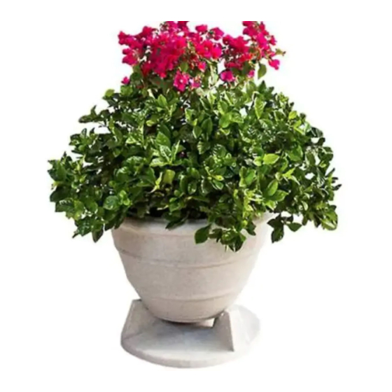
Planter Speakers
Diagram A
© 2021 MSE Audio. Rev. 02.19.2021
Ultra-Fidelity Outdoor Speakers
INSTALL INSTRUCTIONS
Diagram B
Advertisement

Subscribe to Our Youtube Channel
Related Manuals for Rockustics Planter Speakers 298SOP65GG


Summary of Contents for Rockustics Planter Speakers 298SOP65GG
- Page 1 INSTALL INSTRUCTIONS Planter Speakers Please read the following instructions carefully before installing your Rockustics ® Planter speaker. If you have any questions regarding installation that are not answered in the following directions, please contact your local sound contractor or the Rockustics ®...
-
Page 2: Cautions And Maintenance
Planter Diagram C Cautions and Maintenance All Rockustics speakers are sealed and fully weatherproof. However, DO NOT place speakers where the speaker will be in the path of a sprinkler system. Sprinklers typically have a high water pressure level that can damage speaker cones if hit directly. - Page 3 64 Watt transformer (request Frequency response is measured in prior to order) for use in commercial ap- half space plications. Continuous power rating, EIA-426-B test 2.83 Volts at a distance of 1 meter. © 2011 Rockustics. All rights reserved. PN TS-XT550 REV 06.07.11...
- Page 4 508 mm data to dealers, engineers and designers. (20 in.) in diameter by 431.8 mm (17 in.) in All data are available from Rockustics or at height. The unit shall weigh no more than www.rockustics.com.
Need help?
Do you have a question about the Planter Speakers 298SOP65GG and is the answer not in the manual?
Questions and answers