Table of Contents
Advertisement
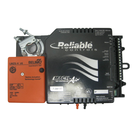
Ideal for low-point VAV applications
where unrestricted programming
and full data acquisition are
Can be networked on the main
or subnetwork, rendering easy
communication with the full line of
Reliable Controls™
Three user configurable universal
or triac inputs and outputs;
Onboard velocity sensor and
relocatable damper actuator;
SMART-Sensors™ support.
Communication ports include
VAV Controller
required.
products.
Flash EEPROM;
SMART-Net™ and
EIA-485 Network.
2002 Reliable Controls™ Corporation
MACH-Air
Quick Start Guide
The MACH-Air™ is a
high-performance,
fully programmable
DDC controller
designed to meet the
needs of Variable Air
Volume control within
the Reliable Controls™
MACH-System.
..
.people and technology
™
you can rely on
TM
Advertisement
Table of Contents

Related Manuals for Reliable Controls MACH-Air


Summary of Contents for Reliable Controls MACH-Air
- Page 1 ™ MACH-Air VAV Controller Quick Start Guide The MACH-Air™ is a Ideal for low-point VAV applications high-performance, where unrestricted programming fully programmable and full data acquisition are DDC controller required. designed to meet the needs of Variable Air Can be networked on the main...
- Page 2 MACH-Air™ VAV Controller Document Conventions Reliable Controls™ Quick Start Guides use several conventions to aid in your understanding of the material and to make information more readily accessible. These conventions are outlined below. Software menu items will appear in bold faced type and follow the form: Start>Programs>Reliable Controls™>RC-Studio™...
- Page 3 Reliable Controls™ Corporation makes no representation with respect to this manual. In no event shall Reliable Controls™ Corporation be liable for damages, direct or incidental, arising out of or related to the use of this manual. No part of this document may be reproduced or transmitted in any form or by any means, without the express written permission of Reliable Controls™...
- Page 4 MACH-Air VAV Controller 2001 Reliable Controls Corporation...
-
Page 5: Table Of Contents
Outputs........20 MACH-Air™ Universal Outputs ... . . 20 MA-T™... - Page 6 MACH-Air™ VAV Controller Calibration ......27 Calibration Procedure (RC-Toolkit ™ ) ..28 ™...
-
Page 7: Package Contents
MACH-Air™ VAV Controller Package Contents Package Contents Your new MACH-Air™ VAV controller package should include: 1. The MACH-Air™ VAV controller. 2. Self-tapping mounting screw taped to the controller body. 2002 Reliable Controls™ Corporation... -
Page 8: Getting Started
MACH-Air™ controller. This document is intended to provide installation and setup procedures for first time users. The most important concepts that are crucial to the reliable operation of the MACH-Air™ are introduced. Product Overview The MACH-Air™ VAV controller features: Three user configurable universal inputs. - Page 9 MACH-Air™ VAV Controller Getting Started MACH-Air™ VAV Controller Features Damper Actuator Power Connection EIA-485 Network Connection Output Connection Input Connection SMART-Net Port Velocity Sensor MACH-Air ™ Connector Wiring MACH-Air ™ -T Connector Wiring 2002 Reliable Controls™ Corporation...
- Page 10 ! Inputs four, five, and six (IN4, IN5, IN6) and outputs four and five (OUT4, OUT5) are dedicated to air flow and motor functions (see Inputs and Outputs). ! Variable one (VAR1) of the MACH-Air™ is reserved for the ‘Flow Calibration Constant’. ! MACH-Air™ network settings, such as baud rate, network type, controller address, and last panel must be configured using the SETUP-Tool™...
-
Page 11: Installation
Installation The MACH-Air™ VAV controller is typically mounted directly on the sheet metal of an air duct: Mount the MACH-Air™ VAV controller on the mixing box. Clamp the motor to the damper control shaft using the universal U-bolt clamp assembly. -
Page 12: Optional Cover
MACH-Air™ VAV Controller Installation Optional Cover The MACH-Air™ VAV controller may be ordered with an optional connector cover that protects the connector terminal from exposure or interference. The connector terminal is located on the right side of the controller. MACH-Air without optional cover ™... -
Page 13: Orientation
The controller can be set to open with counter-clockwise rotation (see Outputs). Reverse Mounting The MACH-Air™ motor can be rotated with the motor drive on the top or bottom side of the controller assembly. Remove three bolts on the underside of the assembly to rotate the motor. - Page 14 MACH-Air™ VAV Controller Installation MACH-Air™ VAV Controller Orientations 2002 Reliable Controls™ Corporation...
-
Page 15: Physical Dimensions
[1.95] 22.4 [0.88] This controller is intended to be installed in accordance with the National Electric Code or the Canadian Electric Code, Part 1, and in a manner acceptable to the local authority having jurisdiction. 2002 Reliable Controls™ Corporation... -
Page 16: Power Wiring
2. Connect the neutral wire to the GND connection at the right side of the controller. 3. The neutral wire of the 24 VAC must be connected to the Earth Refer to Page 3 for a complete ground. connector wiring diagram. 2002 Reliable Controls™ Corporation... - Page 17 MACH-Air™ VAV Controller Power Wiring MACH-Air™ VAV Controller Power Wiring 2002 Reliable Controls™ Corporation...
-
Page 18: Status Led
MACH-Air™ VAV Controller Status LED Status LED The MACH-Air™ VAV controller status LED provides power indication and shows the EIA-485 network activity. The status LED is located just below the SMART-Net™ port at the bottom right side of the controller. - Page 19 Self check failure. (6 flashes / second) (Service required) Continuous, very rapid Network error. flashing (at 96 Hz) (Holding network token) On for half second, off for Network error. half second. (Check connections and settings) 2002 Reliable Controls™ Corporation...
-
Page 20: Workstation Connection
RC-Studio™ software. The workstation must be connected to a MACH1™, MACH2™,or MACH-Global™ controller, or ETHER-Net™ portal that resides on the same system as the MACH-Air™ VAV controller. No EIA-232 port is available on the MACH-Air™ VAV controller. -
Page 21: Direct
MACH-Air™ VAV Controller Workstation Connection Direct If direct communication is absolutely necessary between a workstation and the MACH-Air™ VAV controller, a PC-Link (EIA-485/EIA-232 converter) and the RC-DOS™ software can be used. Direct Communications X-Port converter Operator Workstation MACH-Air ™ 2002 Reliable Controls™ Corporation... -
Page 22: Inputs
MACH-Air™ VAV Controller Inputs Inputs The MACH-Air™ VAV controller is designed with six inputs: ! Three inputs are configurable universal inputs ! Three inputs are dedicated inputs Universal Inputs Inputs one, two, and three (IN1, IN2, IN3) are universal inputs that can be configured as digital (binary) or analogue (modulating). -
Page 23: Dedicated Inputs
Input six (IN6) is dedicated to indicate damper at end of position. When the input displays a ‘Yes’, the motor is currently at the end of position. 2002 Reliable Controls™ Corporation... -
Page 24: Jumper Settings
J1, J2, and J3 respectively. Four different input types can be set using the jumper shunts: 0-5 VDC 4-20 mA Thermistor Thermistor setting is a 10k Ohm pullup to +5 VDC. Dry contact Smart Net Status Input Jumper Shunts 2002 Reliable Controls™ Corporation... - Page 25 MACH-Air™ VAV Controller Inputs Input Jumper Settings Jumper Selection No Jumper 0-5 VDC Inside Jumper* Thermistor/Dry Contact Outside Jumper 4-20 mA * Factory Default (shown above) 2002 Reliable Controls™ Corporation...
-
Page 26: Outputs
MACH-Air™ VAV Controller Outputs Outputs The MACH-Air™ VAV controller is designed with five outputs, which can be ordered in two different configurations: ! MACH-Air™ with three user configurable universal outputs, and two dedicated outputs. ! MACH-Air-T™ with one universal output, one single stage triac output, one dual stage triac output and two dedicated outputs. -
Page 27: Ma-T™ Single Stage Triac Outputs
Ampere. (relay). Connect the device as shown in the diagram below. Triacs switch AC voltage only. A OUT+ A OUT - LOAD TRIAC 1 RTN-T1 24VAC 120VAC DS1-T1 Transformer DS1-T2 RTN-DS1 IN1 + 2002 Reliable Controls™ Corporation... -
Page 28: Ma-T™ Dual Stage Triac Outputs
ON when the output is commanded to 10 volts. Connect the two stages as shown in the diagram below. A OUT+ A OUT - TRIAC 1 RTN-T1 STAGE 1 DS1-T1 DS1-T2 STAGE 2 24VAC 120VAC RTN-DS1 Transformer IN1 + 2002 Reliable Controls™ Corporation... -
Page 29: Dedicated Outputs
Output five (OUT5) is dedicated to control ‘the direction of rotation to close’ with respect to the damper. ! Default = counter clockwise = ‘No’ ! Set to ‘Yes’ if the damper is required to close with a clockwise rotation 2002 Reliable Controls™ Corporation... -
Page 30: Setup-Tool
‘voice cable’ connection between the SETUP-Tool™ and the SMART-Net™ port on the MACH-Air™ VAV controller. The SETUP -Tool™ is powered by the MACH-Air™ VAV controller and does not require a separate external power supply. The SETUP-Tool™ has two modes of operation, MSET and Flow mode. -
Page 31: Mset Mode
MSet Mode With the SETUP-Tool™ in MSet mode, the buttons are used to change the address, baud- rate, network type, last panel Each MACH-Air™ VAV controller settings, and to calibrate the must be MSet using the actuator motor. SETUP-Tool™. 1. Select the parameter to change 2. -
Page 32: Flow Mode
When the SETUP-Tool™ is in flow mode all the buttons (with the exception of the ‘MTR-CAL’ button) are user programmable to enable a variety of air flow related functions. The buttons are assigned to points on the MACH-Air™ VAV controller with the assistance of the RC-Studio™ software application. -
Page 33: Motor Calibration
MACH-Air™ VAV Controller Motor Calibration Motor Calibration The MACH-Air™ VAV controller must be calibrated for proper motor operation. The calibration drives the motor to determine the full range of actuation and then stores this range in memory. To calibrate the motor, the MACH-Air™ VAV controller must be properly installed and connected to the damper that it will be controlling. -
Page 34: Calibration Procedure
Select the appropriate communications port and enter the password ‘June’ before clicking ‘OK’. 5. Select MACH-Air™ Calibration. 6. Enter the panel number of the MACH-Air™ VAV controller of interest and then select Calibrate Motor. The motor will automatically move to the fully closed position, then proceed to the fully open position. -
Page 35: Smart-Sensor
Connection ™ SMART-Sensor Connection The MACH-Air™ VAV controller supports up to four SMART-Sensors™ (Part# - SS). The SMART-Sensors™ are ideal for measuring space/zone temperatures and providing user level adjustments to temperature set points. See the SMART-Sensor™ Quick Start Guide for installation details. -
Page 36: Networking
MACH-Air™ VAV Controller Networking Networking The Reliable Controls MACH-System™ can be networked in a variety of ways, which are discussed in the ‘Networking the Reliable Controls MACH-System™’ document. When employing EIA-485 networks with the MACH-Air™ VAV controller, the next three sections are relevant. -
Page 37: End-Of-Line Termination
To determine the network extremities, calculate the maximum network length between any two controllers. The controllers at the extremities must be terminated. To terminate a MACH-Air™ VAV controller, remove the black ABS cover and install If the network is not terminated EOL jumpers J15 and J16. -
Page 38: Real Time Clock
The MACH-Air™ VAV controller does not contain a Real Time Clock (RTC) chip. ! To access real time functions using the MACH-Air™ VAV controller, it is necessary to network the MACH-Air™ VAV controller to a controller or portal that has RTC capabilities, (e.g. MACH1™, MACH2™, MACH- Global™... -
Page 39: Technical Specifications
6 VA nominal power consumption Maximum Energy 12 VA/12 W Consumption Connector 12-pole K1 connector (24 VAC, GND) Indication One LED, green Communications EIA-485 Serial Connector, 2-pin, 76.8 kbps max. RJ-11 connector, 6 pin SMART-Net™ 2002 Reliable Controls™ Corporation... - Page 40 22.9 cm L x 13.4 cm W x 6.3 cm H (9” L x 4.8” W x 2.5” H) Weight 0.7 kg (1.8 lb) Cover FR/ABS NEMA Type 1 Mounting Motor Bracket and #4 screw 2002 Reliable Controls™ Corporation...
- Page 41 Analogue Input 0-5 VDC, 4-20 mA, thermistor Digital Input Dry contact Ω Input Impedance 15 k on 0-5 VDC range Input Type Selection Jumper configurable Pulse counting 40 Hz maximum Overload protection 24 VAC over-voltage protection 2002 Reliable Controls™ Corporation...
- Page 42 MACH-Air™ VAV Controller Technical Specifications Outputs Quantity Three universal outputs (MACH-Air™) Converter 8-bit D-A Analogue Output 0-12 VDC, scalable in software Digital Output 0-12 VDC Output Power 75 mA, 12 VDC maximum Overload Protection 24 VAC over-voltage and short protection MA-T™...
- Page 43 MACH-Air™ VAV Controller Notes 2002 Reliable Controls™ Corporation...
- Page 44 Toll Free 1(877)475-9301 Tel (250) 475-2036 Fax (250) 475-2096 Toll Free 1(877)475-9301 Tel (250) 475-2036 Fax (250) 475-2096 MACH-Air™ Rev 1.9 PLC 09/17/02 w w w . r e l i a b l e - c o n t r o l s . c o m...
Need help?
Do you have a question about the MACH-Air and is the answer not in the manual?
Questions and answers