
Subscribe to Our Youtube Channel
Related Manuals for KROFtools 9817

Summary of Contents for KROFtools 9817
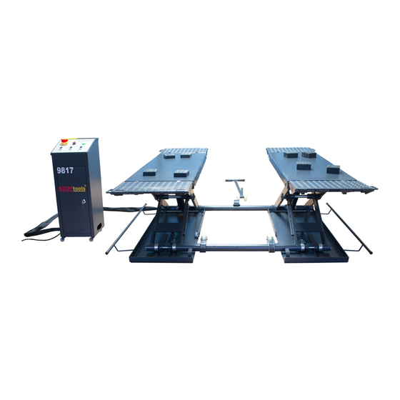
- Page 1 Instructions and maintenance manual FOR HYDRAULIC SCISSOR LIFT 3T REF 9817 The specifications stated on this manual are not binding. We reserve the right to change the specification without notice...
- Page 3 Disclaimer No part of this book shall be reproduced, stored in retrieval, or transmitted by any means, electronic, mechanical, photocopying, recording, or otherwise without the written permission of While every precaution has been taken in the preparation of this manual, the publisher assumes no responsibility for errors or omissions.
- Page 4 Loose clothing should not be worn when operating the Lift. Any personnel with long hair operating the Lift should use a protection cap as precautionary safety measures. ******* IMPORTANT NOTE******** The following must be observed at all times to ensure correct use of the hoist. Follow regular maintenance schedule as per manual ■...
-
Page 5: Table Of Contents
• We continually seeks advancements in product design and quality. Therefore, while this manual contains the most current product information available at the time of printing, there may be minor discrepancies between your lift and this manual. lf you have any questions concerning this manual, please consult your dealer or call manufacturing. -
Page 6: Transport & Unpacking
OWNER'S MANUAL AND/OR WHEN MADE NECESSARY BY MECHANICAL CONDITIONS. Please read the following important notice carefully before operate the lift. Lifting Capacity: 3000KG WARNING: When the lift is working, any personnel is not allowed to get in the lift and the car, it could result in severe injury or death! DO NOT PUT ANYTHING ON THE SAFETY LOCK. -
Page 7: Specifications
SPECIFICATIONS Lifting capacity 3000kg Max. Lifting height 1000mm height 110mm Min. Overall width 1760mm 1400-2004mm Platform length Space between platforms 700mm Lifting time 60 sec Noise 70db (A) 1m Operating temperature 10ºC - +50ºC Work environment: Closed roam 200-240V 50/60Hz 1Ph. -
Page 8: Description
lf the install at out, it must be protected by some kind of roofing against rain. The following work environment conditions are applicable Relative humidity: from 30-95% without condensation. Temperature: 10-50ºC. WARNING The machine can not be operated in explosive atmospheres. WORKPLACE REQUIREMENTS Machine need space: requirements are 3200X2000mm with a minimum distance from... -
Page 9: Installation
NOTE lt is the main parts figures above. More detailed components and assembly please see exploded view. INSTALLATION Connecting pipes There are two pipes from the hydraulic pump as shown in the figure. (X) is a electric wire and used for the safety lock. (Y) is a hydraulic oil pipe and used for the hydraulic cylinders. -
Page 10: Operation
Enter hydraulic oi/ Remove the motor box off, and then turn the oil cap anti-clockwise to open the oil inlet. Fill in the hydraulic oil 30# from the oil inlet as shown in the figure. Oil inlet Oil inlet NOTE •... -
Page 11: Storing
Press the UP button, the lift will go up When the lift is working (lifting a car), remember: any personnel do not get in the lift and the car, it could result in severe injury or death! Press the DOWN button, the platform will go down STORING lf the machine has to be stored for a long time you should :... -
Page 12: Maintenance
• Grease all the parts that could be damaged if they dry out. • Empty hydraulic oil tank and wrap the machine in a sheet of protective plastic to prevent dust from reaching the internai working parts. lf the machine has to work again after a long storing period, it is necessary to: •... -
Page 13: Hydaulic Power Unit
3. Exploded drawings with the data needed to order spare parts PERIODIC MAINTENANCE OPERATION FREQUENCY To keep the lift working at full efficiency, follow the indicated maintenance schedule. The manufacturer will not be responsible and will not honor the warranty as a result of non-compliance with the instructions indicated above. - Page 14 Gheck that the locking system works properly. Grease all the moving parts. EVERY 6-MONTHS... HYDRAULIC Gheck the contamination or aging levei of the oil. Gontaminated oil is the main cause of malfunctions of the valves and leads to a brief service life of the gear pumps. EVERY 12- MONTHS General check:...
-
Page 15: Hydraulic System
3. lmmediately find the cause of any abnormalities (excessive noise, overheating, leaking fluids, etc) 4. Pay special attention to lifting parts (cylinders) and safety devices 5. Use all the documentation supplied by the manufacturer (wiring diagrams, etc) HYDRAULIC SYSTEM 1. Oil cylinder 1 2. - Page 16 ELECTRIC SYSTEM 220VAC/ l PH 5111\ 220VAC / 50HZ/ 2. 2KW SWITCH (BREAKER) VALVE ALTERNATING CONTACTOR ELECTRIC MOTOR PLAY DETECTOR TORCH relay UPSWITCH FU1-3 DONE SWITCH fuse LIMIT SWITCH TRANSFORMERS Refer to the above circuit diagram for the connection of the motor. The rotation of the motor should be towards the direction of the pump, if not, amend the connection of motor.
-
Page 17: Structure Diagram
STRUCTURE DIAGRAM... - Page 19 Dó ---- · Name Name Code Code Platform Internai arm Internai arm Roller Externai arm Shaft for roller Base Cylinder Platform Bearing 2515 <D Ramp Circlip Ramp Support Base Roller Tube support Shaft for ramp Upper lock Bolt M6 Lock <D Lock fix Circlip...
Need help?
Do you have a question about the 9817 and is the answer not in the manual?
Questions and answers