Advertisement
Quick Links
I nstruction M anual: B ronco_M egacooler_8185_R1
Last Updated: April 28
th
, 2022
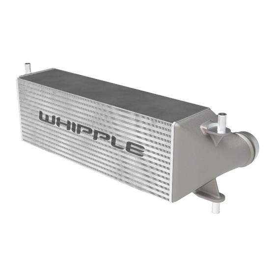
2021 AN D UP FORD BRONCO
M EGACOOLER UP GRADE
2.3L/ 2.7L ECOBOOST
W HI P P LE P AR T NUM BER #EB-8185
W HI PPLE SUPERCHARGER S
3292 N ORTH W EBER AVE
FRESN O, CA 93722
TEL 559.442.1261
FAX 559.442.4153
W W W .W HI PPLESUPERCHARGERS.COM
P R EM I UM FUEL ONLY (91 OCTANE OR BETTER ALW AYS) R ON+M ON/ 2
CALI FOR NI A AI R R ESCOUR CE BOAR D EXECUTI VE OR DER #P ENDI NG
COMPETITION BASED PRODUCT MAY BE USED SOLELY ON VEHICLES USED IN SANCTIONED COMPETITION WHICH
MAY NEVER BE USED UPON A PUBLIC ROAD OR HIGHWAY
P age 1 of 16
w w w .w hipplesuperchargers.com
Advertisement

Subscribe to Our Youtube Channel
Related Manuals for Whipple EB-8185


Summary of Contents for Whipple EB-8185
- Page 1 , 2022 2021 AN D UP FORD BRONCO M EGACOOLER UP GRADE 2.3L/ 2.7L ECOBOOST W HI P P LE P AR T NUM BER #EB-8185 W HI PPLE SUPERCHARGER S 3292 N ORTH W EBER AVE FRESN O, CA 93722 TEL 559.442.1261...
-
Page 2: Recommended Tools And Supplies
If necessary, vacuum around engine to remove any foreign material. CAUTION Identify Kit Components: Before beginning installation, identify all the components of your Whipple Kit and ensure all items are present and undamaged. P age 2 of 16 w w w .w hipplesuperchargers.com... -
Page 3: Safety Precautions
Do not wear loose clothing or jewelry that can be caught in rotating or moving parts. • **NOTI CE: Installation of Whipple products signifies that you have read this document and have agreed to the terms stated within. It’s the purchaser’s responsibility to follow all installation instruction guidelines and safety procedures supplied with the product as it’s received by the purchaser to determine the compatibility of the product with the vehicle or the device the... -
Page 4: Installation Instructions
I NSTALLATI ON I NSTR UCTI ONS It is strongly recommended that you read through this guide before you begin installing the Whipple Kit. Using an air hose, blow off any loose dirt or debris from engine compartment. If really dirty, then steam clean the engine compartment before proceeding to the next step. - Page 5 I nstruction M anual: B ronco_M egacooler_8185_R1 Last Updated: April 28 , 2022 Release the CAC inlet pipe by spreading the retainer ends outward. Position the retainer ends in the notches locking the retainer in the open position and position aside the CAC inlet pipe. Release the CAC outlet pipe by spreading the retainer ends outward.
- Page 6 I nstruction M anual: B ronco_M egacooler_8185_R1 Last Updated: April 28 , 2022 If equipped, remove the bolts and front bumper bar using a T40 socket. Remove the push pins, release the clips and remove the front bumper trim panel. Remove the bolts and the front bumper using a 15mm socket.
- Page 7 I nstruction M anual: B ronco_M egacooler_8185_R1 Last Updated: April 28 , 2022 Release the CCM cover top clips and remove cover. Disconnect the lower active grill shutter actuator electrical connector. Remove the (4) bolts and the lower active grille shutter unit using 8mm socket. P age 7 of 16 w w w .w hipplesuperchargers.com...
- Page 8 I nstruction M anual: B ronco_M egacooler_8185_R1 Last Updated: April 28 , 2022 If equipped, remove the tow hook shields. Gently release the CCM grommets from the active grille shutter CCM bracket, then remove CCM from bracket. Disconnect CCM wiring connector from CCM. NOTE: If not equipped with CCM, disregard. With the aid of a 2 person, remove (4) bolts from the CAC/tow hook brackets to lower CAC out of vehicle.
- Page 9 I nstruction M anual: B ronco_M egacooler_8185_R1 Last Updated: April 28 , 2022 Remove the CAC isolators from CAC. Transfer to new CAC. (If equipped) Remove the (1) bolt and dislodge the holding clips. Using factory bolt, transfer to new CAC. Torque to 62 in-lbs.
- Page 10 I nstruction M anual: B ronco_M egacooler_8185_R1 Last Updated: April 28 , 2022 Remove the CCM bracket from active grill shutter using an 8mm socket. Transfer CCM bracket to supplied CCM bracket assembly using the (3) 6mm x 10mm HHFCS fasteners. Torque to 96 in-lb using a 10mm socket. Slide CCM module back on bracket.
- Page 11 I nstruction M anual: B ronco_M egacooler_8185_R1 Last Updated: April 28 , 2022 Mount the shutter motor to the bracket assembly using the (2) supplied zip-ties. Secure CCM wiring using same zip ties for a clean installation. Install the new CCM bracket assembly to vehicle using the (4) factory fasteners. Torque to 62 in-lb using 8mm socket.
- Page 12 I nstruction M anual: B ronco_M egacooler_8185_R1 Last Updated: April 28 , 2022 Reconnect CCM wiring connector to CCM. Reinstall plastic cover over CCM bracket, this will NOT fit after bumper installation. Reconnect the lower active grill shutter actuator electrical connector. Install the stock bolts and the front bumper using a 15mm socket, torque to 81 ft-lb.
- Page 13 I nstruction M anual: B ronco_M egacooler_8185_R1 Last Updated: April 28 , 2022 Reinstall the push pins and front bumper trim panel. Reinstall the front bumper bar with the factory (8) bolts using a T40 socket. Torque to 25 ft-lb. Reconnect the front bumper electrical connector.
- Page 14 I nstruction M anual: B ronco_M egacooler_8185_R1 Last Updated: April 28 , 2022 Reinstall the fasteners and the engine front under shield. Torque to 124 in-lbs. Remove the fastener and the air intake duct. Remove the 4 bolts securing airbox lid to airbox. Remove stock filter by lifting up and away. P age 14 of 16 w w w .w hipplesuperchargers.com...
- Page 15 I nstruction M anual: B ronco_M egacooler_8185_R1 Last Updated: April 28 , 2022 Install the CARB legal decal next to the OEM emission decal located under the hood. Start the vehicle, check for any leaks or check engine lights. NOTE: If the CCM (cruise control module) needs to be aligned, perform the cruise control radar alignment procedure before the front bumper is installed.
- Page 16 I nstruction M anual: B ronco_M egacooler_8185_R1 Last Updated: April 28 , 2022 NOTE: Measurement must be taken from the non-raised side of the CCM. Keeping the combination square level on the face of the CCM, adjust the pitch by turning the adjustment screw until the CCM is vertical and level. NOTE: The horizontal alignment for the CCM (cruise control module) is a software calibration check that is performed by the scan tool to insure the CCM (cruise control module) radar is pointed straight.
Need help?
Do you have a question about the EB-8185 and is the answer not in the manual?
Questions and answers