Table of Contents
Advertisement
Quick Links
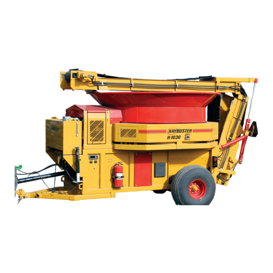
Operating Instructions and Parts Reference
H-1030
PTO Driven Tub Grinder
0500154 • M
2020
ay
TM
P
roduct
D
T
I
I
ura
ech
nDusTrIes
nTernaTIonal
Po B
1940, J
ox
amesTown
T
: (701) 252-4601• F
el
ax
.
.
www
DuraTechInDusTrIes
neT
I
nformatIon
I
.
nc
, nD 58402-1940
: (701) 252-0502
•
.
.
www
hayBusTer
com
Advertisement
Table of Contents
Troubleshooting

Related Manuals for Haybuster H-1030

Summary of Contents for Haybuster H-1030
- Page 1 Operating Instructions and Parts Reference H-1030 PTO Driven Tub Grinder roduct nformatIon nDusTrIes nTernaTIonal Po B 1940, J , nD 58402-1940 amesTown : (701) 252-4601• F : (701) 252-0502 • 0500154 • M 2020 DuraTechInDusTrIes hayBusTer...
- Page 2 A Tradition of Innovation Since 1966...
- Page 3 H-1030 PTO Driven Tub Grinder as of the date of publication. DuraTech Industries reserves the right to make updates to the machine from time to time. Even in the event of such updates, you should still find this manual to be appropriate for the safe operation and maintenance of your unit.
- Page 4 A Tradition of Innovation Since 1966...
- Page 5 • Section 2.1, “Pre-Operation Inspection”. Appropriate use of unit The H-1030 Tilt Tub Grinder is designed to grind material into more palatable or manageable rations for your operation. It has multiple uses: Grind most types of hay • Big round bales • Loose hay...
- Page 6 WARNING: The OPERATOR IS RESPONSIBLE for the safety of the operator and those in the surrounding area. Operators and those observing the operation of the H-1030 Tub Grinder are required to wear head, eye, and ear protection, No loose clothing is allowed.
-
Page 7: Table Of Contents
T A B L E O F C O N T E N T S Part 1: Operating Instructions ........1 Introduction ................. 2 Purpose ..................2 Section 1: Safety ................. 4 1.1 Safety-alert symbols ..................4 1.2 Operator - personal equipment ................6 1.3 Machine safety labels .................. - Page 8 3.5 Balanced Hammer maintenance and replacement .......... 71 3.6 Dodge Rotor bearing installation ..............75 3.7 Cleaning the display unit ................. 77 Section 4: Troubleshooting the H-1030 ........78 4.1 Control parameters for electronic governor ..........78 4.1A Monitor parameters for electronic governor ........79 4.2 Fault Codes ......................
- Page 9 T A B L E O F C O N T E N T S Part 2: Parts Reference ..........85 MAINFRAME ASSEMBLY (FOR S.N. UP TO 1017007030) ......86 MAINFRAME ASSEMBLY (FOR S.N. 1018007130 AND UP) ......92 BELLY SIDESHEETS ................... 98 PLATFORM ASSEMBLY (FOR S.N.
- Page 10 H-1030 TUB GRINDER DOCUMENTATION COMMENT FORM .. 221 APPENDIX A FOLDOUTS ............223 5701061 - H-1030 MACHINE HARNESS (for S.N. Up to 1018012030) ..FO-1 5701174 - H-1030 MACHINE HARNESS (for S.N. 1020012130 and up) ..FO-2 5701170-PTO Tub Tail lights harness (for S.N. 1020012130 and up) ....FO-3...
-
Page 11: Part 1: Operating Instructions
H-1030 PTO Driven Tub Grinder Part 1: Operating Instructions H - 1 0 3 0 T U B G R I N D E R O P E R A T I N G I N S T R U C T I O N S... -
Page 12: Introduction
The purpose of this owner’s manual is to explain maintenance requirements and routine adjustments for the most efficient operation of your H-1030 Tub Grinder. There is also a trouble shooting section that may help in case of problems in the field. Any information not covered in this manual may be obtained from your dealer. - Page 13 Section 3: Describes how to maintain the H-1030 Tub Grinder. • Section 4: Describes how to trouble shoot problems with the H-1030 Tub Grinder. • Part 2: Part’s reference contains diagrams of each assembly, with the part number of each part. A key on the same or facing page contains a description of the part and the quantity used.
-
Page 14: Section 1: Safety
Section 1: Safety The safety of the operator is of great importance to DuraTech Industries/Haybuster. We have provided decals, shield and other safety features to aid you in using your machine safely. In addition, we ask you to be a careful operator who will properly use and service your Haybuster equipment. - Page 15 DANGER: Indicates an imminently hazardous situation that, if not avoided, will result in death or serious injury. This signal word is to be limited to the most extreme situations, typically for machine components that, for functional purposes, cannot be guarded. WARNING: Indicates a potentially hazardous situation that, if not avoided, could result in death or serious injury, and includes hazards...
-
Page 16: Operator - Personal Equipment
Do not operate a H-1030 when you are fatigued. Be alert - If you get tired while operating your H-1030, take a break. Fatigue may result in loss of control. Working with any farm equipment can be strenuous. If you have any condition... -
Page 17: Machine Safety Labels
Machine safety labels The safety decals located on your machine contain important information that will help you operate your equipment. Become familiar with the decals and their locations. DANGER: ROTATING PARTS WITHIN CAN KILL OR DISMEMBER. WAIT FOR ALL MOVEMENT TO STOP BEFORE SERVICING, UNLOADING, OR INSPECTING MACHINE. - Page 18 WARNING: FOR YOUR PROTECTION AND PROTECTION OF OTHERS, PRACTICE THE FOLLOWING SAFETY RULES. BEFORE OPERATING THIS MACHINE, READ THE OPERATOR’S MANUALS SUPPLIED WITH THIS MACHINE AND YOUR TRACTOR. 6500041 CHECK OPERATORS MANUALS TO BE SURE YOUR TRACTOR MEETS THE MINIMUM REQUIREMENTS FOR THIS MACHINE.
- Page 19 WARNING: OVERHEAD CONVEYOR HAZARD TO PREVENT SERIOUS INJURY OR DEATH: 6500214 DO NOT WALK UNDER CONVEYOR AT ANY TIME. STAY CLEAR OF CONVEYOR DURING OPERATION, RAISING, AND LOWERING. LOWER CONVEYOR FULLY BEFORE SERVICING. KEEP OTHERS AWAY. WARNING: HIGH-PRESSURE FLUID HAZARD, TO PREVENT SERIOUS INJURY OR DEATH: •...
- Page 20 WARNING: Noise hazzard. Ear protection required. 6500489 CAUTION: ADJUST TRACTOR DRAWBAR SO THAT DISTANCE FROM THE END OF THE PTO SHAFT ON THE TRACTOR TO THE CENTER OF THE DRAWBAR HITCH PIN IS EQUAL TO THE DISTANCE SHOWN IN DIAGRAM. SEE OWNER’S MANUAL FOR MORE INFORMATION.
-
Page 21: Thrown Objects And Operator Safety
Figure 1.2. Figure 1.1 VIEWED FROM THE REAR OF THE H-1030 NOTE: The difference in the size of the area for side A versus side B. Side B is larger. Dimensioning the size of this area is not practical. The distance a thrown object may travel is dependent on several conditions, including, but not limited to, rotor speed and diameter, condition of the hammers, style of hammers, object mass, object shape, amount of material in the tub, and how the hammer strikes the object. -
Page 22: Shielding
Shielding This H-1030 Tub Grinder is equipped with shielding at all major points of potential injury. All Shields should be kept in place during operation. Bodily injury may occur if the unit is operated without shields. WARNING: Shields are installed for your protection and to keep material off machine parts. Do not operate this Industrial Tub Grinder without shields in place. -
Page 23: Safety Review
Use a tractor that meets the requirements contained in this manual. See Appendix C, Required for Operation, page 63. Make sure the H-1030 Tub Grinder is in good operating condition and that all protective shields are in place and in proper working order. Replace damaged shields before operating. - Page 24 Because it is possible that your H-1030 may be used in dry areas or the presence of combustibles, special precautions should be taken to prevent fires and fire fighting equipment should be readily available.
-
Page 25: Fire Prevention
Fire Prevention Grinding wood, hay, and other products in a tub grinder produces a large amount of potentially combustible material. The risks of fire can be significantly reduced with proper operating and maintenance procedures. This does include frequent removal of dust, debris, and other combustible materials. Most of the products that are ground are dry and the grinding process can produce fine, dusty material. -
Page 26: Fire Extinguishers
TUB GRINDER MAINTENANCE: • Repair any fuel or hydraulic leaks as quickly as they are discovered. Clean up spills immediately. Fuel or oil soaked materials can contribute significantly to the rapid spreading of a fire once it has begun. • Inspect all electrical wiring periodically. -
Page 27: Towing
Make sure all bystanders are clear. Hitch H-1030 Tub Grinder to a tow vehicle with adequate load carrying and braking capacity. Be sure to attach safety chains between tow vehicle and H-1030 Tub Grinder. Tongue weight is 1,925 lbs. (873 kg). -
Page 28: Service And Maintenance
EXPLAINED IN THE OPERATOR’S MANUAL, ADVERTISING LITERATURE OR OTHER DURATECH INDUSTRIES WRITTEN MATERIAL PERTAINING TO THE H-1030 TUB GRINDER. H - 1 0 3 0 T U B G R I N D E R O P E R A T I N G I N S T R U C T I O N S... -
Page 29: Section 2: Operation
There is no substitute for a sound preventative maintenance program and a well-trained operator. To insure long life and economical operation, learn how to operate the H-1030 Tub Grinder and how to use the controls properly. Thoroughly instruct the operator in maintenance and operation of the H-1030 Tub. - Page 30 BEFORE OPERATING CHECKS Before operating the H-1030 Tub Grinder, follow these instructions: Read and understand the operator’s manual. Learn how to operate the controls properly. Do Not let anyone operate without instruction. Know the machine’s safety features and understand the safety precautions.
-
Page 31: Introduction To The Machine
Introduction to the machine 2.2.1 Description of the H-1030 Tub Grinder The Tub Grinder is designed to grind most types of hay, grain and crop residue such as stover and straw. The unit incorporates a number of basic features including the rotating tub, the electronic governor, the rotor and hammer assemblies, the tub chain and drive assemblies, belly auger and discharge conveyor, and the axle and hitch assemblies. -
Page 32: Electronic Governor (For S.n. Up To 1018012030)
2.2.3A Electronic governor (For S.N. Up to 1018012030) General: The Wachendorf A35 with ECU 710 control system will control the Tub and Discharge Conveyor functions of a Tub Grinder. Display Start up screen: Company logo Screen will show when power is applied to the display for approx. 10 sec. Loading screen: Company logo, with loading bar Screen will show right after Start up screen for approx. - Page 33 Home screen: Home Screen will show right after the loading screen. • Tub FWD/REV buttons will control the Tub FWD/REV outputs as described later in this manual. • The Tub Speed gauge will indicate the Tub Speed output with a scale of 0-100. When the Tub Speed button is pressed the Encoder knob will be linked to the Tub Speed setting and the Tub Speed icon will change to red in color.
- Page 34 Hours screen: The Hours screen will be accessed by pressing the next button on the Home Page. • Pressing the Fault Menu button will take the operator to the Fault Screen page. • The Grind Hours window will display the total number of hours the machine has run with the Rotor ON. The Grind Hours can be reset using the Impulse Service Tool (EA1667-E1P REV XX_OEM.icf).
- Page 35 Fault screen: The faults will show up in the fault table screen when they occur. • The ECU column indicates which controller the fault is coming from. This system will have one ECU named ECU-0710. • The Function column indicates which input or output has the fault. Tub Forward Coil Tub Reverse Coil Tub Speed Coil...
- Page 36 FMI 6: Short to Battery A Short to Battery indicates the output wire is touching a positive battery wire. • The Fault Reset button will reset any fault that does not automatically clear (ex. Speed Sensor Fault). Hardkeys: Next • When the Next button is pressed, the display changes to the next screen.
-
Page 37: Electronic Governor (For S.n. 1020012030 & Up)
2.2.3B Electronic governor (For S.N. 1020012030 & Up) General: The Wachendorf A3X with an HFX32 (for sn 1020012130 and up) control system will control the Tub and Discharge Conveyor functions of a Tub Grinder. Display Start up screen: Company logo Screen will show when power is applied to the display for approx. - Page 38 Home screen: Home Screen will show right after the loading screen, when the Home button is pressed from any of the other pages, or when the Encoder is pressed from the Manual Function screen. • Tub FWD/REV buttons will control the Tub FWD/REV outputs as described later in this manual. •...
- Page 39 Manual Function Screen: The Manual Function screen will be accessed by pressing the next button or the encoder on the Home Page. The following functions can be operated on the Manual Function screen. Functions marked with and (8) can also be operated with the radio remote.
- Page 40 Hours screen: The Hours screen will be accessed by pressing the next button on the Manual Function screen. • The Zero Grate button will zero out the Grate Height bar graph on the Home screen. If there is no sensor detected, the Grate Height button will disappear.
- Page 41 Fault screen: The faults will show up in the fault table screen when they occur. The Active Fault screen will display a table indicating the J1939 DM1 message fault codes. The fault codes will be displayed as numerical values unless otherwise specified in the Fault Codes table. (See section 4.2) •...
- Page 42 Hardkeys: Next • When the Next button is pressed, the display changes to the next screen. Home Button • When the home button is pressed the display will go to the home screen. ESC Button • When the ESC button is pressed the display will go back to the previous screen or view. Encoder •...
-
Page 43: Rotor
2.2.4 Rotor The Rotor and screens are the heart of the tub grinder. The rotor on this H-1030 Tub Grinder is equipped with 64 swinging hammers. Dull edges on the hammers and/or screens will result in a loss of capacity and increased horse power requirements. -
Page 44: Screens
2.2.5 Screens All H-1030 Tub Grinders require two screens. They come equipped from the factory with a 2” (5 cm) diameter hole screen and a 3” (8 cm) diameter hole screen. Any combination of hole sizes may be used. As a general rule, use the largest diameter screens capable of doing the job. -
Page 45: Conveyors, Lifting And Folding
2.2.9 Hydraulic Tilt Platform The H-1030 tub grinder can be tilted 90 degrees for access to the rotor, screens, and drive line. Operation of the tub tilt cylinder is performed using the controls for the tractor which is located on the tractor. After using the normal shut down procedures, the hopper platform can then be opened. -
Page 46: Machine Operation
Machine Operation 2.3.1 Tractor Set Up A tractor drawbar and 3-point arms can cause interference with the PTO driveline. This interference can cause serious damage to the PTO guarding and the PTO telescoping members. If this implement is attached to a tractor with a clevis hitch (hammer strap) style drawbar, the hammer-strap must be removed to prevent damage to the PTO guarding and the PTO telescoping members. -
Page 47: How To Hook Up To Tractor
To reduce wear on the PTO shaft knuckle joints, tractor PTO shaft should be in line (parallel) with the H-1030 Tub Grinder. If tractor is equipped with swinging drawbar, adjust so the tractor PTO and H-1030 Tub grinder drive shaft are in line. -
Page 48: How To Operate Machine As A Unit
PTO speed for the tractor to recover automatically if a slug is encountered. GRINDING Place materials to be ground directly into the tub. The best method for filling the H-1030 Tub Grinder is: Engage Rotor and increase speed to 1000 RPM on the PTO shaft Fill the tub about half full of unground materials before starting tub rotation. - Page 49 EAR CORN Grinding ear corn requires a special attachment. This attachment fits directly over the rotor and uses crossbars in the tub to feed corncobs into the rotor. (See Appendix B: H-1030 Specifications under the heading “Options”.) IF LODGING OCCURS Materials may lodge against the side of the tub and not feed down to the rotor.
-
Page 50: Shutdown Procedures
Before working on or near the H-1030 Tub Grinder for any reason, including servicing, inspecting or unclogging machine: Run H-1030 Tub Grinder until discharge conveyor is empty, and grind as much of the material in the tub as possible. Reduce engine speed to idle. -
Page 51: Removing From Storage
Road Transport 2.6.1 Set up to transport Inspect H-1030 Tub Grinder for any loose parts, tools, or any materials. Remove them or fasten them securely to the H-1030 Tub Grinder. To set up the H-1030 for transport, perform the following steps: Fold the conveyor. -
Page 52: Raising The Tub Platform
Raising the Tub Platform WARNING: To prevent serious injury or death, do not tilt platform on unlevel ground or with material in the tub. To raise the tub platform, perform the following steps: Park machine on firm level ground or surface. Remove all material from tub. -
Page 53: A Operation Of The Electronic Governor (For S.n. Up To 1018012030)
2.8A Operation of the Electronic Governor (For S.N. Up to 1018012030) Auto/Manual Mode The system has two modes of operation: Auto Mode and Manual Mode. The mode of operation can be toggled using the Auto/Manual button on the display. Tub Forward •... - Page 54 Warning If the Tub Forward button is pressed on the display, and the Tub Forward output is de-active, and the Tub Reverse output is de-active, and the Rotor Speed input is less than zero, and the system is in Auto Mode: •...
- Page 55 If the Tub Reverse output is active, and the system is switched from Manual Mode to Auto Mode while the Rotor Speed input is zero, or the Tub Forward button is pressed, or the Tub Reverse button is pressed on the display: •...
- Page 56 Tub Speed • The Tub Speed ramp rate and output current will have adjustable parameters in the Impulse Service Tool. Manual Mode: • The Tub will operate in an open loop control mode and will not compensate for rotor rpm changes.
- Page 57 • If the Set Speed button is pressed when the Rotor Speed is greater than the Set Speed Limit High RPM: • The following alarm window will be shown on the display for 3 seconds. • Rotor Speed Min Limit is the RPM where the Tub will stop when the Engine Load is set to 100%.
- Page 58 Conveyor • If the Conveyor button is pressed on the display and the Conveyor Forward output is de-active and the Rotor Speed input is greater than zero or the system is in Manual Mode: • Conveyor Forward output will be activated. •...
-
Page 59: B Operation Of The Electronic Governor (For S.n. 1020012130 And Up)
2.8B Operation of the Electronic Governor (For S.N. 1020012130 and Up) Auto/Manual Mode The system has two modes of operation: Auto Mode and Manual Mode. The mode of operation can be toggled using the Auto/Manual button on the display. Tub Forward •... - Page 60 Warning If the Tub Forward button is pressed on the display, and the Tub Forward output is de-active, and the Tub Reverse output is de-active, and the Rotor Speed input is less than zero, and the system is in Auto Mode: •...
- Page 61 If the Tub Reverse output is active, and the system is switched from Manual Mode to Auto Mode while the Rotor Speed input is zero, or the Tub Forward button is pressed on the display or the radio remote, or the Tub Reverse button is pressed on the display: •...
- Page 62 Tub Speed • The Tub Speed ramp rate and output current will have adjustable parameters in the Impulse Service Tool. Manual Mode: • The Tub will operate in an open loop control mode and will not compensate for rotor rpm changes.
- Page 63 • If the Set Speed button is pressed when the Rotor Speed is greater than the Set Speed Limit High RPM: • The following alarm window will be shown on the display for 3 seconds. • Rotor Speed Min Limit is the RPM where the Tub will stop when the Engine Load is set to 100%.
- Page 64 Conveyor • If the Conveyor button is pressed on the display and the Conveyor Forward output is de-active and the Rotor Speed input is greater than zero or the system is in Manual Mode: • Conveyor Forward output will be activated. •...
-
Page 65: Adjusting The Conveyor Belt Tension
Adjusting the conveyor belt tension The rollers on the discharge conveyor are adjustable to allow for belt stretching and tracking. If the conveyor belt slows down or stops during operation, slippage may be the cause. To eliminate slippage, tighten the adjusting bolts on the conveyor equally. -
Page 66: Adjusting The Conveyor Belt Tracking
2.10 Adjusting the conveyor belt tracking When a new belt is installed: Use only genuine DuraTech Industries parts. Begin by adjusting the drive roller so that the mounting bearings are the same distance from the end of the conveyor frame. This ensures that the roller centerline is square with conveyor frame. Adjust the idler roller tension bolts so that they are equal on both sides of the conveyor. -
Page 67: Adjusting Tub Chain Tension
2.11 Adjusting tub chain tension To adjust the tub chain tension, perform the following steps: lock bolts Loosen (4) bolts holding motor mounting plate. Turn (2) adjusting bolts to set chain tension. Tighten the (4)bolts holding motor mounting plate. chain path adjusting bolts H - 1 0 3 0 T U B G R I N D E R O P E R A T I N G I N S T R U C T I O N S... -
Page 68: Main Drive Belt Adjustment
A spring tensioning system is used on the H-1030 grinder to maintain tension as belts stretch over time. To properly tension the drive belts turn the tensioning rod until the spring caps come into contact with the tubes that the springs are seated into. DO NOT OVERTIGHTEN! The two sheaves must be running parallel, if they are not the belts will not track, premature belt wear or belts running off of the sheaves will result. - Page 69 Figure 2.7 sheave alignment H - 1 0 3 0 T U B G R I N D E R O P E R A T I N G I N S T R U C T I O N S...
-
Page 70: Sensor Test
2.13 Sensor test Set the gap between the sensor and the sprocket to 3/32” (2.4 mm). Sensor resistance should be 900 ohms +/- 10%. 2.14 Belly auger drain covers Belly auger drain covers should be in the open position to allow any moisture to drain out. When grinding small grains the belly auger covers should be in the closed position to keep the grain from spilling out. -
Page 71: Section 3: General Maintenance
Before working on or near the H-1030 Tub Grinder for any reason, including servicing, inspecting or unclogging machine: Run H-1030 Tub Grinder until discharge conveyor is empty, and grind as much of the material in the tub as possible. Reduce engine speed to idle. -
Page 72: Lubrication
If the lubricant is caked and the bearing seems dry, wash the bearing to remove old grease. Repack the bearing. Lubrication CAUTION: Follow normal shutdown procedure before adjusting or lubricating. When operating the H-1030 Tub Grinder during cold weather, perform all lubrication after bearings are at operating temperatures. BEARING LUBRICATION Bearings operating in the presence of dust and water should contain as much grease as speed will permit, since a full bearing with a slight leakage is the best protection against entrance of foreign material. - Page 73 Lubrication Chart H - 1 0 3 0 T U B G R I N D E R O P E R A T I N G I N S T R U C T I O N S...
- Page 74 Figure 3.1 rotor bearing lubrication point rotor bearing lubrication points 1 of 2 (Ref # 3) Figure 3.2 rotor bearing and belly auger bearing lubrication points belly auger bearing lubrication points (Ref # 5) front rotor bearing lubrication points 2 of 2 (Ref # 3) Figure 3.3 tub chain idler pivot lubrication point...
- Page 75 Figure 3.4 tub pivot lubrication points tub pivot lubrication points (Ref #4) Figure 3.5 tub roller, tub pressure roller and roller chain pressure roller roller chain (Ref #12) tub pressure roller (Ref #11) H - 1 0 3 0 T U B G R I N D E R O P E R A T I N G I N S T R U C T I O N S...
- Page 76 Figure 3.6 PTO lubrication points PTO lubrication point (Ref #9) PTO lubrication point (Ref #9) Figure 3.7 discharge conveyor bearings (2 of 4) discharge conveyor bearing lube points (Ref #7) Figure 3.8 discharge conveyor bearings lubrication points (2 of 4) discharge conveyor bearing lube points -one on each side of machine (Ref #7) H - 1 0 3 0 T U B G R I N D E R...
- Page 77 Figure 3.9 conveyor lift pivot lubrication points conveyor lift pivot lube points -one on each side of machine (Ref #8) Figure 3.10 jack shaft and bull wheel jack shaft bearings bearings lubrication points lubrication points (Ref #1) bull wheel bearings lubrication points (Ref #6) H - 1 0 3 0 T U B G R I N D E R...
-
Page 78: Hydraulic System
Hydraulic system CAUTION: Lack of proper oil level in the reservoir tank will cause system to heat under continuous running. Check the hydraulic oil level daily and replace as necessary. Hydraulic Oil Reservoir Capacity: 60 gallons All machines have been pre-run at the factory to insure all functions are preforming correctly. -
Page 79: Screens
CAUTION: Follow normal shutdown procedure before entering tub to do any service work. To change screens on the H-1030, perform the following steps: Raise the tub platform using the following steps WARNING: To prevent serious injury or death, do not tilt platform on unlevel ground or with material in the tub. -
Page 80: Hammermill Maintenance
Hammermill maintenance Visually examine the mill to see if any of the internal parts show excessive wear. These parts should include rotor discs and the holes in the discs that support the rods. Enlarged holes can cause rods to break or bend. Also check rods, rod locking or retaining devices, hammers, screens, screen tracks and hold downs, main shaft, platform locking devices, hinges or anything else that could wear and perhaps fail and causing damage to the hammermill and/or personnel safety if not properly maintained. -
Page 81: Balanced Hammer Maintenance And Replacement
Balanced Hammer maintenance and replacement H - 1 0 3 0 T U B G R I N D E R O P E R A T I N G I N S T R U C T I O N S... - Page 82 H - 1 0 3 0 T U B G R I N D E R O P E R A T I N G I N S T R U C T I O N S...
- Page 83 CAUTION: Before entering tub to do any service work, raise the tub platform following the instructions on page 31 under the heading “Raising the Tub Platform”. After raising the tub platform follow procedures 5 through 8 of the normal shutdown procedure on page 28. We recommend the following: Always replace hammers in pairs, 180 degrees apart.
- Page 84 Figure 3.11 hammer spacing chart for the H-1030 H - 1 0 3 0 T U B G R I N D E R O P E R A T I N G I N S T R U C T I O N S...
-
Page 85: Dodge Rotor Bearing Installation
3.6 Dodge Rotor bearing installation WARNING: To ensure the rotor is not unexpectedly started, turn off and lock out or tag the power sources before proceeding. Failure to observe these precautions could result in bodily injury. NOTE: Bearing housing caps and bases are not interchangeable and must be matched with mating half. - Page 86 MOUNTING Install the non expansion unit first. Apply a coating of light oil or other rust inhibitor to the adapter area of the shaft. Before mounting bearing to shaft, remove lockplate from bearing and turn locknut counterclockwise one to two turns to allow adapter to expand fully.
-
Page 87: Cleaning The Display Unit
a) Slide lockplate over shaft and align tang of lockplate with slot in adapter sleeve. b) Find a locknut hole that aligns with a lockplate hole. If the closest locknut hole is beyond a lockplate hole, then tighten, not loosen, the locknut to meet a lockplate hole c) Insert lockwasher and tighten button head screws to lock assembly. -
Page 88: Section 4: Troubleshooting The H-1030
Section 4: Troubleshooting the H-1030 4.1 Control parameters for electronic governor H - 1 0 3 0 T U B G R I N D E R O P E R A T I N G I N S T R U C T I O N S... -
Page 89: A Monitor Parameters For Electronic Governor
4.1A Monitor parameters for electronic governor (For S.N. Up to 1018012030) (For S.N. 1020012130 and Up) H - 1 0 3 0 T U B G R I N D E R O P E R A T I N G I N S T R U C T I O N S... -
Page 90: Fault Codes
Fault Codes H - 1 0 3 0 T U B G R I N D E R O P E R A T I N G I N S T R U C T I O N S... -
Page 91: General Troubleshooting
General Troubleshooting H - 1 0 3 0 T U B G R I N D E R O P E R A T I N G I N S T R U C T I O N S... -
Page 92: Appendix A: Warranty
Appendix A: Warranty DuraTech Industries International Inc. warrants to the original purchaser for 12 months from purchase date that this product will be free from defects in material and workmanship when used as intended and under normal maintenance and operating conditions. This warranty is limited to the replacement of any defective part or parts returned to our factory in Jamestown, North Dakota, USA, within thirty (30) days of failure. -
Page 93: Appendix B: H-1030 Specifications
....................24 in. (60.96 cm) Wide Tub size @ base ................99.5 in. (2.43 m) Tub Depth ..................44.1 in. (1.12 m) Tub Drive ..................Electro-Hydraulic Options AVAILABLE OPTIONS FOR DURATECH INDUSTRIES H-1030 TUB GRINDER: • Ear Corn Kit • Geyser Plate •... -
Page 94: Appendix C: Required For Operation
Appendix C: Required for operation Tractor - 150 to 315 hp 1000 RPM PT0 Shaft Dual Hydraulics, double acting control valve, 8 GPM, 1500 psi (46 lpm x 10,345 Kpa) See also Section 2.3.1, Tractor Set Up. H - 1 0 3 0 T U B G R I N D E R O P E R A T I N G I N S T R U C T I O N S... -
Page 95: Part 2: Parts Reference
H-1030 PTO Driven Tub Grinder Part 2: Parts Reference... -
Page 96: Mainframe Assembly (For S.n. Up To 1017007030)
M A I N F R A M E A S S E M B L Y ( F O R S . N . U P T O 1 0 1 7 0 0 7 0 3 0 ) H - 1 0 3 0 T U B G R I N D E R P A R T S R E F E R E N C E... - Page 97 M A I N F R A M E A S S E M B L Y ( F O R S . N . U P T O 1 0 1 7 0 0 7 0 3 0 ) ITEM PART QTY.
- Page 98 M A I N F R A M E A S S E M B L Y ( F O R S . N . U P T O 1 0 1 7 0 0 7 0 3 0 ) H - 1 0 3 0 T U B G R I N D E R P A R T S R E F E R E N C E...
- Page 99 M A I N F R A M E A S S E M B L Y ( F O R S . N . U P T O 1 0 1 7 0 0 7 0 3 0 ) ITEM PART QTY.
- Page 100 M A I N F R A M E A S S E M B L Y ( F O R S . N . U P T O 1 0 1 7 0 0 7 0 3 0 ) H - 1 0 3 0 T U B G R I N D E R P A R T S R E F E R E N C E...
- Page 101 M A I N F R A M E A S S E M B L Y ( F O R S . N . U P T O 1 0 1 7 0 0 7 0 3 0 ) ITEM PART QTY.
-
Page 102: Mainframe Assembly (For S.n. 1018007130 And Up)
M A I N F R A M E A S S E M B L Y ( F O R S . N . 1 0 1 8 0 0 7 1 3 0 A N D U P ) H - 1 0 3 0 T U B G R I N D E R P A R T S R E F E R E N C E... - Page 103 M A I N F R A M E A S S E M B L Y ( F O R S . N . 1 0 1 8 0 0 7 1 3 0 A N D U P ) ITEM PART QTY.
- Page 104 M A I N F R A M E A S S E M B L Y ( F O R S . N . 1 0 1 8 0 0 7 1 3 0 A N D U P ) H - 1 0 3 0 T U B G R I N D E R P A R T S R E F E R E N C E...
- Page 105 M A I N F R A M E A S S E M B L Y ( F O R S . N . 1 0 1 8 0 0 7 1 3 0 A N D U P ) ITEM PART QTY.
- Page 106 M A I N F R A M E A S S E M B L Y ( F O R S . N . 1 0 1 8 0 0 7 1 3 0 A N D U P ) H - 1 0 3 0 T U B G R I N D E R P A R T S R E F E R E N C E...
- Page 107 M A I N F R A M E A S S E M B L Y ( F O R S . N . 1 0 1 8 0 0 7 1 3 0 A N D U P ) ITEM PART QTY.
-
Page 108: Belly Sidesheets
B E L L Y S I D E S H E E T S H - 1 0 3 0 T U B G R I N D E R P A R T S R E F E R E N C E... - Page 109 B E L L Y S I D E S H E E T S ITEM PART QTY. PART DESCRIPTION 4502974 SH\SIDE\BELLY 4800053 BOLT\CRG\3/8X1\NC 4900002 NUT\HEX\3/8\NC 5000001 WASH\FLAT\3/8 5000019 WASH\LOCK\3/8 4502978 KIT\SH\SIDE\BOX\RTR\1030 H - 1 0 3 0 T U B G R I N D E R P A R T S R E F E R E N C E...
-
Page 110: Platform Assembly (For S.n. Up To 1015001030)
P L A T F O R M A S S E M B L Y ( F O R S . N . U P T O 1 0 1 5 0 0 1 0 3 0 ) H - 1 0 3 0 T U B G R I N D E R P A R T S R E F E R E N C E... - Page 111 P L A T F O R M A S S E M B L Y ( F O R S . N . U P T O 1 0 1 5 0 0 1 0 3 0 ) ITEM PART QTY.
-
Page 112: Platform Assembly Details (For S.n. Up To 1015001030)
P L A T F O R M A S S E M B L Y D E T A I L S ( F O R S . N . U P T O 1 0 1 5 0 0 1 0 3 0 ) H - 1 0 3 0 T U B G R I N D E R P A R T S R E F E R E N C E... - Page 113 P L A T F O R M A S S E M B L Y D E T A I L S ( F O R S . N . U P T O 1 0 1 5 0 0 1 0 3 0 ) ITEM PART QTY.
-
Page 114: Platform Assembly (For S.n. 1016001130 And Up)
P L A T F O R M A S S E M B L Y ( F O R S . N . 1 0 1 6 0 0 1 1 3 0 A N D U P ) H - 1 0 3 0 T U B G R I N D E R P A R T S R E F E R E N C E... - Page 115 P L A T F O R M A S S E M B L Y ( F O R S . N . 1 0 1 6 0 0 1 1 3 0 A N D U P ) ITEM PART QTY.
-
Page 116: Platform Assembly Details (For S.n. 1016001130 And Up)
P L A T F O R M A S S E M B L Y D E T A I L S ( F O R S . N . 1 0 1 6 0 0 1 1 3 0 A N D U P ) H - 1 0 3 0 T U B G R I N D E R P A R T S R E F E R E N C E... - Page 117 P L A T F O R M A S S E M B L Y D E T A I L S ( F O R S . N . 1 0 1 6 0 0 1 1 3 0 A N D U P ) ITEM PART QTY.
-
Page 118: Bull Wheel Assembly
B U L L W H E E L A S S E M B L Y H - 1 0 3 0 T U B G R I N D E R P A R T S R E F E R E N C E... - Page 119 B U L L W H E E L A S S E M B L Y ITEM PART QTY. PART DESCRIPTION 1400605 SHVE\5V-8\21.2\85V2120J 1400642 BUSH\QD\J\2-3/4 1600102 V-BELT\5VP850 2000509 BRG\PB\2-3/4\E\DODGE 2000510 BRG\PB\2\2BOLT 4501170 BOLT\FRM\TGHTNR\CHAIN\TUB 4502330 WHL\BULL\FRM\OFFSET 4502331 SHFT\WHL\BULL\OFFSET 4502333 SHIM\BRG\WHL\BULL 4502334 SHM\THN\BRG\WHL\BLL 4502338...
-
Page 120: Rotor Assembly
R O T O R A S S E M B L Y H - 1 0 3 0 T U B G R I N D E R P A R T S R E F E R E N C E... - Page 121 R O T O R A S S E M B L Y ITEM PART QTY. PART DESCRIPTION 2001052 BRG\PB\3\IMPRL\NON-EXP 2001053 BRG\PB\3\IMPRL\EXP 3600834 FLG\3ID\1610\DRVLIN 4500142 NUT\CYL\3-1/2 4502322 WASH\THRUST\ROTOR\H1130 4502669 SHIM\BRG 4502787 SPCR\SHOCK\HMMR\RTR 4502788 SPCR\HMMR\RTR 4702292 PL\RTR\MVBL\6IDX15-3/4\1-1/4ROD 4704292 WASHER\PL\MOVEABLE\RTR 4705473 SHFT\RTR\3-1/2X61-7/8\3”BRG 4705474 PL\RTR\3/8X3-1/2ID\1-1/4RDS\TPPD 4705475...
-
Page 122: Pump Drive Line
P U M P D R I V E L I N E H - 1 0 3 0 T U B G R I N D E R P A R T S R E F E R E N C E... - Page 123 P U M P D R I V E L I N E ITEM PART QTY. PART DESCRIPTION 4702627 SPKT\60\TPR\20\2012\REV 1100064 CHAIN\60DBL\CL 1100193 CHAIN\60DBL\19 1400637 SHVE\5V-8\9.25\F 2001052 BRG\PB\3\IMPRL\NON-EXP 2001053 BRG\PB\3\IMPRL\EXP 3600833 1610 DRIVELINE 17-1/2” COMP. 3600834 FLG\3ID\1610\DRVLIN 4200142 PUMP\HYD\TNDM\1.78CIDX1.3CID 4502665 BRKT\PUMP 4502784 SPKT\SNSR...
-
Page 124: Tub Drive Assembly
T U B D R I V E A S S E M B L Y H - 1 0 3 0 T U B G R I N D E R P A R T S R E F E R E N C E... - Page 125 T U B D R I V E A S S E M B L Y ITEM PART QTY. PART DESCRIPTION 1000237 SPKT\80\B\40\2-1/4\1/2KW 1100070 CHAIN\2080\CL 1100071 CHAIN\2080\OL 1100310 CHAIN\2080\165 4200121 MTR\HYD\40.6\1000\2-1/4\1-5/16FOR 4501328 BOLT\HEX\3X4X8-1/2 4501331 RLLR\DR\TUB 4501383 BRKT\SPRING\ 4501705 BRKT\RLLR\TNSN 4501707 BRKT\MTR\DRV\TUB 4502797 SPCR\DRIVE...
-
Page 126: Tub Assembly
T U B A S S E M B L Y H - 1 0 3 0 T U B G R I N D E R P A R T S R E F E R E N C E... - Page 127 T U B A S S E M B L Y ITEM PART QTY. PART DESCRIPTION 4502397 TUB\1030 4502409 AGTTR\TUB\FIN\10 4502410 AGTTR\TUB\FIN\14 4800106 BOLT\HEX\5/8X1-1/2 4900005 NUT\HEX\5/8\NC 5000003 WASH\LOCK\5/8 4705469 TUB\ASSY\1030 H - 1 0 3 0 T U B G R I N D E R P A R T S R E F E R E N C E...
-
Page 128: Belly Auger Assembly
B E L L Y A U G E R A S S E M B L Y H - 1 0 3 0 T U B G R I N D E R P A R T S R E F E R E N C E... - Page 129 B E L L Y A U G E R A S S E M B L Y ITEM PART QTY. PART DESCRIPTION 1400659 CPLR\RIGID\1.5X1.25 2000587 BRG\FLG\2”-BLT\SSCRW 2000588 BRG\FLG\2-1/2\4-BLT\D-LOCK 3900010 MTR\HYD\24\2000\SAE;A 4502312 ADJSTR\BRG\FR 4502393 AUGER\RIGHT 4502395 AUGER\LEFT\1030 4502427 SH\SIDE\PAN\CNVYR 4502603 CVR\HOLE\DRN 4502666 SPCR\BRG\AGR\CNVYR...
-
Page 130: Lower Discharge Conveyor Assembly
L O W E R D I S C H A R G E C O N V E Y O R A S S E M B L Y H - 1 0 3 0 T U B G R I N D E R P A R T S R E F E R E N C E... - Page 131 L O W E R D I S C H A R G E C O N V E Y O R A S S E M B L Y ITEM PART QTY. PART DESCRIPTION 1700255 BELT\CNVYR\24X513\CLEATED 2000303 BRG\FLG\1-1/2\BOLT 4100030 PIN 1”...
-
Page 132: Upper Discharge Conveyor Assembly (For S.n. Up To 1017007030)
U P P E R D I S C H A R G E C O N V E Y O R A S S E M B L Y ( F O R S . N . U P T O 1 0 1 7 0 0 7 0 3 0 ) H - 1 0 3 0 T U B G R I N D E R P A R T S R E F E R E N C E... - Page 133 U P P E R D I S C H A R G E C O N V E Y O R A S S E M B L Y ( F O R S . N . U P T O 1 0 1 7 0 0 7 0 3 0 ) ITEM PART QTY.
-
Page 134: Upper Discharge Conveyor Assembly (For S.n. 1018007130 And Up)
U P P E R D I S C H A R G E C O N V E Y O R A S S E M B L Y ( F O R S . N . 1 0 1 8 0 0 7 1 3 0 A N D U P ) H - 1 0 3 0 T U B G R I N D E R P A R T S R E F E R E N C E... - Page 135 U P P E R D I S C H A R G E C O N V E Y O R A S S E M B L Y ( F O R S . N . 1 0 1 8 0 0 7 1 3 0 A N D U P ) ITEM PART QTY.
-
Page 136: Hydraulic Oil Tank Assembly
H Y D R A U L I C O I L T A N K A S S E M B L Y H - 1 0 3 0 T U B G R I N D E R P A R T S R E F E R E N C E... - Page 137 H Y D R A U L I C O I L T A N K A S S E M B L Y ITEM PART QTY. PART DESCRIPTION 3800301 FTG\1-5/16MOR\PLUG 4400043 FILTER\HYDRAULIC\RETURN\IN-TANK ELEMENT 4400074 4400066 GAUGE\FLTR\25PSI\1/8NPTF\COLOR CODED 4400067 FLTR\SCRN\2-1/2MORX1-7/8FOR\30GPM\ST30-100-RV3 4400071 VENT\W/LOCK\CAP\HYD 4502424...
-
Page 138: Tandum Hydraulic Pump
T A N D U M H Y D R A U L I C P U M P ITEM PART NO. QTY. PART DESCRIPTION 4200142 PUMP\HYD\TNDM\1.78CIDX1.3CID 4200161 PUMP\SEAL\KIT\4200142 H - 1 0 3 0 T U B G R I N D E R P A R T S R E F E R E N C E... - Page 139 A Tradition of Innovation Since 1966 H - 1 0 3 0 T U B G R I N D E R P A R T S R E F E R E N C E...
-
Page 140: Hydraulic Valve - 4000541 View 1 (For S.n. Up To 1018012030)
H Y D R A U L I C V A L V E - 4 0 0 0 5 4 1 V I E W 1 ( F O R S . N . U P T O 1 0 1 8 0 1 2 0 3 0 ) H - 1 0 3 0 T U B G R I N D E R P A R T S R E F E R E N C E... - Page 141 H Y D R A U L I C V A L V E - 4 0 0 0 5 4 1 V I E W 1 ( F O R S . N . U P T O 1 0 1 8 0 1 2 0 3 0 ) ITEM PART QTY.
-
Page 142: Hydraulic Valve - 4000598 View 2 (For S.n. Up To 1018012030)
H Y D R A U L I C V A L V E - 4 0 0 0 5 9 8 V I E W 2 ( F O R S . N . U P T O 1 0 1 8 0 1 2 0 3 0 ) H - 1 0 3 0 T U B G R I N D E R P A R T S R E F E R E N C E... - Page 143 H Y D R A U L I C V A L V E - 4 0 0 0 5 9 8 V I E W 2 ( F O R S . N . U P T O 1 0 1 8 0 1 2 0 3 0 ) ITEM PART QTY.
-
Page 144: Hydraulic Valve - 4000598 View 1 (For S.n. 1020012130 And Up)
H Y D R A U L I C V A L V E - 4 0 0 0 5 9 8 V I E W 1 ( F O R S . N . 1 0 2 0 0 1 2 1 3 0 A N D U P ) H - 1 0 3 0 T U B G R I N D E R P A R T S R E F E R E N C E... - Page 145 H Y D R A U L I C V A L V E - 4 0 0 0 5 9 8 V I E W 1 ( F O R S . N . 1 0 2 0 0 1 2 1 3 0 A N D U P ) ITEM PART QTY.
-
Page 146: Hydraulic Valve - 4000541 View 2 (For S.n. 1020012130 And Up)
H Y D R A U L I C V A L V E - 4 0 0 0 5 4 1 V I E W 2 ( F O R S . N . 1 0 2 0 0 1 2 1 3 0 A N D U P ) H - 1 0 3 0 T U B G R I N D E R P A R T S R E F E R E N C E... - Page 147 H Y D R A U L I C V A L V E - 4 0 0 0 5 4 1 V I E W 2 ( F O R S . N . 1 0 2 0 0 1 2 1 3 0 A N D U P ) ITEM PART QTY.
-
Page 148: Oil Tank Hydraulics (For S.n. Up To 1018012030)
O I L T A N K H Y D R A U L I C S ( F O R S . N . U P T O 1 0 1 8 0 1 2 0 3 0 ) H - 1 0 3 0 T U B G R I N D E R P A R T S R E F E R E N C E... - Page 149 O I L T A N K H Y D R A U L I C S ( F O R S . N . U P T O 1 0 1 8 0 1 2 0 3 0 ) ITEM PART QTY.
-
Page 150: Oil Tank Hydraulics (For S.n. 1020012130 And Up)
O I L T A N K H Y D R A U L I C S ( F O R S . N . 1 0 2 0 0 1 2 1 3 0 A N D U P ) H - 1 0 3 0 T U B G R I N D E R P A R T S R E F E R E N C E... - Page 151 O I L T A N K H Y D R A U L I C S ( F O R S . N . 1 0 2 0 0 1 2 1 3 0 A N D U P ) ITEM PART QTY.
-
Page 152: Tandum Pump Hydraulics
T A N D U M P U M P H Y D R A U L I C S H - 1 0 3 0 T U B G R I N D E R P A R T S R E F E R E N C E... - Page 153 T A N D U M P U M P H Y D R A U L I C S ITEM PART QTY. PART DESCRIPTION 3800277 FTG\1-1/16MORX1-1/16MJIC\ST 3800470 FTG\1-5/8MORX1-5/8MJIC\ST 3800532 FTG\1-1/16MORX1-1/16MJIC\45 3800741 FTG\1-5/8MORX1-5/8MJIC\90 4200142 PUMP\HYD\TNDM\1.78CIDX1.3CID 3701595 HOSE\HYD\1-1/4X49\1-5/8FJICX1-5/8FJIC SUPPLY PORT FRONT PUMP TO RIGHT TANK PORT SCREEN 3701595 HOSE\HYD\1-1/4X49\1-5/8FJICX1-5/8FJIC SUPPLY PORT REAR PUMP TO LEFT TANK SCREEN...
-
Page 154: Aux. Valve Hydraulics View A (For S.n. Up To 1018012030)
A U X . V A L V E H Y D R A U L I C S V I E W A ( F O R S . N . U P T O 1 0 1 8 0 1 2 0 3 0 ) H - 1 0 3 0 T U B G R I N D E R P A R T S R E F E R E N C E... - Page 155 A U X . V A L V E H Y D R A U L I C S V I E W A ( F O R S . N . U P T O 1 0 1 8 0 1 2 0 3 0 ) ITEM PART QTY.
-
Page 156: Aux. Valve Hydraulics View A (For S.n. 1020012130 And Up)
A U X . V A L V E H Y D R A U L I C S V I E W A ( F O R S . N . 1 0 2 0 0 1 2 1 3 0 A N D U P ) H - 1 0 3 0 T U B G R I N D E R P A R T S R E F E R E N C E... - Page 157 A U X . V A L V E H Y D R A U L I C S V I E W A ( F O R S . N . 1 0 2 0 0 1 2 1 3 0 A N D U P ) ITEM PART QTY.
-
Page 158: Aux. Valve Hydraulics View B (For S.n. Up To 1018012030)
A U X . V A L V E H Y D R A U L I C S V I E W B ( F O R S . N . U P T O 1 0 1 8 0 1 2 0 3 0 ) H - 1 0 3 0 T U B G R I N D E R P A R T S R E F E R E N C E... - Page 159 A U X . V A L V E H Y D R A U L I C S V I E W B ( F O R S . N . U P T O 1 0 1 8 0 1 2 0 3 0 ) ITEM PART QTY.
-
Page 160: Aux. Valve Hydraulics View B (For S.n. 1020012130 And Up)
A U X . V A L V E H Y D R A U L I C S V I E W B ( F O R S . N . 1 0 2 0 0 1 2 1 3 0 A N D U P ) H - 1 0 3 0 T U B G R I N D E R P A R T S R E F E R E N C E... - Page 161 A U X . V A L V E H Y D R A U L I C S V I E W B ( F O R S . N . 1 0 2 0 0 1 2 1 3 0 A N D U P ) ITEM PART QTY.
-
Page 162: Aux. Valve Hydraulics View C (For S.n. Up To 1018012030)
A U X . V A L V E H Y D R A U L I C S V I E W C ( F O R S . N . U P T O 1 0 1 8 0 1 2 0 3 0 ) H - 1 0 3 0 T U B G R I N D E R P A R T S R E F E R E N C E... - Page 163 A U X . V A L V E H Y D R A U L I C S V I E W C ( F O R S . N . U P T O 1 0 1 8 0 1 2 0 3 0 ) ITEM PART QTY.
-
Page 164: Aux. Valve Hydraulics View C (For S.n. 1020012130 And Up)
A U X . V A L V E H Y D R A U L I C S V I E W C ( F O R S . N . 1 0 2 0 0 1 2 1 3 0 A N D U P ) H - 1 0 3 0 T U B G R I N D E R P A R T S R E F E R E N C E... - Page 165 A U X . V A L V E H Y D R A U L I C S V I E W C ( F O R S . N . 1 0 2 0 0 1 2 1 3 0 A N D U P ) ITEM PART QTY.
-
Page 166: Tub Rotation Hydraulics (For S.n. Up To 1018012030)
T U B R O T A T I O N H Y D R A U L I C S ( F O R S . N . U P T O 1 0 1 8 0 1 2 0 3 0 ) H - 1 0 3 0 T U B G R I N D E R P A R T S R E F E R E N C E... - Page 167 T U B R O T A T I O N H Y D R A U L I C S ( F O R S . N . U P T O 1 0 1 8 0 1 2 0 3 0 ) ITEM PART QTY.
-
Page 168: Tub Rotation Hydraulics (For S.n. 1020012130 And Up)
T U B R O T A T I O N H Y D R A U L I C S ( F O R S . N . 1 0 2 0 0 1 2 1 3 0 A N D U P ) H - 1 0 3 0 T U B G R I N D E R P A R T S R E F E R E N C E... - Page 169 T U B R O T A T I O N H Y D R A U L I C S ( F O R S . N . 1 0 2 0 0 1 2 1 3 0 A N D U P ) ITEM PART QTY.
-
Page 170: Tub Tilt Hydraulics (For S.n. Up To 1018012030)
T U B T I L T H Y D R A U L I C S ( F O R S . N . U P T O 1 0 1 8 0 1 2 0 3 0 ) H - 1 0 3 0 T U B G R I N D E R P A R T S R E F E R E N C E... - Page 171 T U B T I L T H Y D R A U L I C S ( F O R S . N . U P T O 1 0 1 8 0 1 2 0 3 0 ) ITEM PART QTY.
-
Page 172: Tub Tilt Hydraulics (For S.n. 1020012130 And Up)
T U B T I L T H Y D R A U L I C S ( F O R S . N . 1 0 2 0 0 1 2 1 3 0 A N D U P ) H - 1 0 3 0 T U B G R I N D E R P A R T S R E F E R E N C E... - Page 173 T U B T I L T H Y D R A U L I C S ( F O R S . N . 1 0 2 0 0 1 2 1 3 0 A N D U P ) ITEM PART QTY.
-
Page 174: Belly Auger Hydraulics View A
B E L L Y A U G E R H Y D R A U L I C S V I E W A H - 1 0 3 0 T U B G R I N D E R P A R T S R E F E R E N C E... -
Page 175: Belly Auger Hydraulics View B
B E L L Y A U G E R H Y D R A U L I C S V I E W B H - 1 0 3 0 T U B G R I N D E R P A R T S R E F E R E N C E... - Page 176 A Tradition of Innovation Since 1966 H - 1 0 3 0 T U B G R I N D E R P A R T S R E F E R E N C E...
-
Page 177: Belly Auger Hydraulics
B E L L Y A U G E R H Y D R A U L I C S ITEM PART QTY. PART DESCRIPTION 3800277 FTG\1-1/16MORX1-1/16MJIC\ST 3800280 FTG\1-1/16MJICX1-1/16FJIC\90\SW 3800472 FTG\7/16MORX7/16MJIC\90 3800535 FTG\7/8MORX1-1/16MJIC\90 3800669 FTG\MORXMJIC\45 3900010 MTR\HYD\24\2000\SAE;A 4700777 CLMP\HOSE\1/2 3800988 FTG\7/16MJICX7/16MJICX7/16MOR\TEE 7501337 CLMP\HOSE\CUSH\3/4... -
Page 178: Conveyor Lift And Fold Cylinder Hydraulics
C O N V E Y O R L I F T A N D F O L D C Y L I N D E R H Y D R A U L I C S H - 1 0 3 0 T U B G R I N D E R P A R T S R E F E R E N C E... - Page 179 C O N V E Y O R L I F T A N D F O L D C Y L I N D E R H Y D R A U L I C S ITEM PART QTY. PART DESCRIPTION 3800428 MNFLD\DBL;TEE\BLK\3/4FOR...
-
Page 180: Conveyor Flow Control Valve Hydraulics
C O N V E Y O R F L O W C O N T R O L V A L V E H Y D R A U L I C S H - 1 0 3 0 T U B G R I N D E R P A R T S R E F E R E N C E... - Page 181 C O N V E Y O R F L O W C O N T R O L V A L V E H Y D R A U L I C S ITEM PART QTY. PART DESCRIPTION 3800277 FTG\1-1/16MORX1-1/16MJIC\ST 3800463 FTG\1-1/16MORX1-1/16MJICX1-1/16MJIC\RUN;TEE...
-
Page 182: Discharge Conveyor Orbit Motor Hydraulics
D I S C H A R G E C O N V E Y O R O R B I T M O T O R H Y D R A U L I C S H - 1 0 3 0 T U B G R I N D E R P A R T S R E F E R E N C E... - Page 183 D I S C H A R G E C O N V E Y O R O R B I T M O T O R H Y D R A U L I C S ITEM PART QTY. PART DESCRIPTION 3800527 FTG\7/8MORX1-1/16MJIC\ST...
-
Page 184: Pressure Gauges Hydraulics (For S.n. Up To 1018012030)
P R E S S U R E G A U G E S H Y D R A U L I C S ( F O R S . N . U P T O 1 0 1 8 0 1 2 0 3 0 ) H - 1 0 3 0 T U B G R I N D E R P A R T S R E F E R E N C E... - Page 185 P R E S S U R E G A U G E S H Y D R A U L I C S ( F O R S . N . U P T O 1 0 1 8 0 1 2 0 3 0 ) ITEM PART QTY.
-
Page 186: Pressure Gauges Hydraulics (For S.n. 1020012130 And Up)
P R E S S U R E G A U G E S H Y D R A U L I C S ( F O R S . N . 1 0 2 0 0 1 2 1 3 0 A N D U P ) H - 1 0 3 0 T U B G R I N D E R P A R T S R E F E R E N C E... -
Page 187: Pressure Gauges Hydraulics (For S.n. 1020012130 And Up)
P R E S S U R E G A U G E S H Y D R A U L I C S ( F O R S . N . 1 0 2 0 0 1 2 1 3 0 A N D U P ) ITEM PART QTY. - Page 188 J A C K S H A F T & B U L L W H E E L G R E A S E L I N E S H - 1 0 3 0 T U B G R I N D E R P A R T S R E F E R E N C E...
-
Page 189: Jack Shaft & Bull Wheel Grease Lines
J A C K S H A F T & B U L L W H E E L G R E A S E L I N E S ITEM PART QTY. PART DESCRIPTION 2000509 BRG\PB\2-3/4\E\DODGE 2000510 BRG\PB\2\2BOLT 2000587 BRG\FLG\2”-BLT\SSCRW 2000588 BRG\FLG\2-1/2\4-BLT\D-LOCK... -
Page 190: Rotor & Belly Conveyor Grease Lines
R O T O R & B E L L Y C O N V E Y O R G R E A S E L I N E S H - 1 0 3 0 T U B G R I N D E R P A R T S R E F E R E N C E... - Page 191 R O T O R & B E L L Y C O N V E Y O R G R E A S E L I N E S ITEM PART QTY. PART DESCRIPTION 2000509 BRG\PB\2-3/4\E\DODGE 2000510 BRG\PB\2\2BOLT 2000587 BRG\FLG\2”-BLT\SSCRW 2000588 BRG\FLG\2-1/2\4-BLT\D-LOCK...
-
Page 192: Wheels And Hubs
W H E E L S A N D H U B S H - 1 0 3 0 T U B G R I N D E R P A R T S R E F E R E N C E... - Page 193 W H E E L S A N D H U B S ITEM PART QTY. PART DESCRIPTION 2600053 TIRE\16.5LX16.1SL\14PLY 2600649 WHL\8-BOLT\16.1X14C\8K 2900125 HUB\H817\CONE\OUTER 2900126 HUB\H817\CUP\OUTER 2900127 CUP\INNER\WHL:HUB(48510 2900128 HUB\H817\CONE\INNER 2900140 HUB\8-BOLT\W/RACES\W/NUTS 2900130 CAP\DUST\H817 2900131 SEAL\GREASE\H817 4900053 NUT\CASTLE\1-1/4\NF 4900114 NUT\TAPER\WHEEL\5/8\NF 5000065 WASH\2.5OD\1.25ID\224 8101600...
-
Page 194: Orbit Motor
O R B I T M O T O R H - 1 0 3 0 T U B G R I N D E R P A R T S R E F E R E N C E... - Page 195 O R B I T M O T O R ITEM PART QTY. PART DESCRIPTION 3900014 MTR\HYD\9.6\2000\1-1/4SH 6200004 KEY\SQ\5/16X1-1/2 3900011 MTG FLG(2000 SER) 7501005 KIT\SEAL\2000ORBIT 3900010 MTR\HYD\11.9\2000\SAE;A;> 6200004 KEY\SQ\5/16X1-1/2 3900011 MTG FLG(2000 SER) 7501005 KIT\SEAL\2000ORBIT 4200121 PUMP\EATON\25501-RSA\B MT 7501148 SEAL\KIT\PUMP\25500\EATON H - 1 0 3 0 T U B G R I N D E R P A R T S R E F E R E N C E...
-
Page 196: 3600833 Drive Line Assembly
3 6 0 0 8 3 3 D R I V E L I N E A S S E M B L Y H - 1 0 3 0 T U B G R I N D E R P A R T S R E F E R E N C E... - Page 197 3 6 0 0 8 3 3 D R I V E L I N E A S S E M B L Y ITEM PART QTY. PART DESCRIPTION 3600857 FLANGE YOKE 1610 3600858 SLIP YOKE 1610 3600859 YOKE SHAFT 1610 3600860 JOURNAL AND BEARING KIT 1610 3600833...
-
Page 198: 3600831 Pto Assembly
3 6 0 0 8 3 1 P T O A S S E M B L Y ITEM PART QTY. PART DESCRIPTION 3600831 PTO\COMP\77E\20SP\1-3/4 3600738 CROSS&BRG\77E\WSLR 3600741 YOKE\77E\1-3/4\LOCK\AUTO 3600775 LOCK\SAFTY;SLD\KIT\1-3/4\77E 3600852 JOINT&TUBE\77E\3600831 3600853 YOKE&SHAFT\77E\3600831 3600854 GUARD\PTO\1-3/4\77E\20SPLN\OUTER 3600855 GUARD\PTO\1-3/4\77E\20SPLN\INNER 3600856 YOKE&TUBE&SLEEVE\77E\3600831 3600871 PTO\HALF\TRACTOR\3600831... -
Page 199: 3600832 Pto Assembly
3 6 0 0 8 3 2 P T O A S S E M B L Y ITEM PART QTY. PART DESCRIPTION 3600832 PTO\COMP\77E\21SP\1-3/8 3600738 CROSS&BRG\77E\WSLR 3600777 LOCK\SAFTY;SLD\KIT\1-3/8\77E 3600852 JOINT&TUBE\77E\3600831 3600853 YOKE&SHAFT\77E\3600831 3600854 GUARD\PTO\1-3/4\77E\20SPLN\OUTER 3600855 GUARD\PTO\1-3/4\77E\20SPLN\INNER 3600856 YOKE&TUBE&SLEEVE\77E\3600831 3600861 YOKE\77E\1-3/8\LOCK\AUTO 3600872 PTO\HALF\TRACTOR\3600832... -
Page 200: Pressure Roller Assembly
P R E S S U R E R O L L E R A S S E M B L Y ITEM PART QTY. PART DESCRIPTION 4501313 BRKT\RLLR\PRESS\10” 2900055 SEAL/WHEEL HUB(16069) 2900018 CONE\OUTER\WHL;HUB 67048 2900004 CUP\OUTER\WHL;HUB 67010 2900061 OUTERCONE/WHL;HUB(11949 5000094 WASH\SPNDL\5/8 4900112... -
Page 201: Tub Roller Bearing Assembly
T U B R O L L E R B E A R I N G A S S E M B L Y ITEM PART QTY. PART DESCRIPTION 1200013 RLLR\TUB\1-1/2\W/O FLANGE 2000584 BRG\CYL\1-1/2\DLOK 4702007 BRG\PB\RLLR\TUB\ASY\W/BRG INSRT (includes #2) NOT SHOWN 4800930 BOLT\FLG\SERR\1/2X2\NC 4900100 NUT\FLG\TPLCK\1/2\NC H - 1 0 3 0 T U B G R I N D E R... -
Page 202: Hydraulic Cylinder Seals And Other Items
H Y D R A U L I C C Y L I N D E R S E A L S A N D O T H E R I T E M S H - 1 0 3 0 T U B G R I N D E R P A R T S R E F E R E N C E... - Page 203 H Y D R A U L I C C Y L I N D E R S E A L S A N D O T H E R I T E M S ITEM PART QTY. PART DESCRIPTION 4100144 CYL\HYD\4X30\1-3/4 ROD\CLEVIS ENDS\O-RING PORTS 4100180...
-
Page 204: Mill Grate - 5 Bar - 2-1/4 (For S.n. Up To 1018012030)
M I L L G R A T E - 5 B A R - 2 - 1 / 4 ( F O R S . N . U P T O 1 0 1 8 0 1 2 0 3 0 ) H - 1 0 3 0 T U B G R I N D E R P A R T S R E F E R E N C E... - Page 205 M I L L G R A T E - 5 B A R - 2 - 1 / 4 ( F O R S . N . U P T O 1 0 1 8 0 1 2 0 3 0 ) ITEM PART QTY.
-
Page 206: Mill Grate - 5 Bar - 2-1/4 (For S.n. 1020012130 And Up)
M I L L G R A T E - 5 B A R - 2 - 1 / 4 ( F O R S . N . 1 0 2 0 0 1 2 1 3 0 A N D U P ) H - 1 0 3 0 T U B G R I N D E R P A R T S R E F E R E N C E... - Page 207 M I L L G R A T E - 5 B A R - 2 - 1 / 4 ( F O R S . N . 1 0 2 0 0 1 2 1 3 0 A N D U P ) ITEM PART QTY.
-
Page 208: Electrical Parts (For S.n. Up To 1018012030)
E L E C T R I C A L P A R T S ( F O R S . N . U P T O 1 0 1 8 0 1 2 0 3 0 ) H - 1 0 3 0 T U B G R I N D E R P A R T S R E F E R E N C E... - Page 209 E L E C T R I C A L P A R T S ( F O R S . N . U P T O 1 0 1 8 0 1 2 0 3 0 ) ITEM PART QTY.
-
Page 210: Electrical Parts (For S.n. 1020012130 And Up)
E L E C T R I C A L P A R T S ( F O R S . N . 1 0 2 0 0 1 2 1 3 0 A N D U P ) H - 1 0 3 0 T U B G R I N D E R P A R T S R E F E R E N C E... - Page 211 E L E C T R I C A L P A R T S ( F O R S . N . 1 0 2 0 0 1 2 1 3 0 A N D U P ) ITEM PART QTY.
-
Page 212: Grain Hopper (Option)
G R A I N H O P P E R ( O P T I O N ) H - 1 0 3 0 T U B G R I N D E R P A R T S R E F E R E N C E... - Page 213 G R A I N H O P P E R ( O P T I O N ) ITEM PART QTY. PART DESCRIPTION 4501349 HPPR\GRAIN\ASSY\COMPLETE 4501335 HPPR\GRAIN 4501339 CVR\RTR\HPPR\GRAIN 4501341 CVR\END\HPPR\GRAIN 4800003 BOLT\HEX\3/8X1 4800034 BOLT\HEX\3/8X1-1/2 4900002 NUT\HEX\3/8\NC 5000001 WASH\FLAT\3/8 5000019 WASH\LOCK\3/8 6500452...
- Page 214 G R A I N H O P P E R ( O P T I O N ) H - 1 0 3 0 T U B G R I N D E R P A R T S R E F E R E N C E...
- Page 215 G R A I N H O P P E R ( O P T I O N ) ITEM PART QTY. PART DESCRIPTION 4501349 HPPR\GRAIN\ASSY\COMPLETE 4501335 HPPR\GRAIN 4501339 CVR\RTR\HPPR\GRAIN 4501341 CVR\END\HPPR\GRAIN 4800003 BOLT\HEX\3/8X1 4800034 BOLT\HEX\3/8X1-1/2 4900002 NUT\HEX\3/8\NC 5000001 WASH\FLAT\3/8 5000019 WASH\LOCK\3/8 6500452...
-
Page 216: Ear Corn Kit (Option)
E A R C O R N K I T ( O P T I O N ) H - 1 0 3 0 T U B G R I N D E R P A R T S R E F E R E N C E... - Page 217 E A R C O R N K I T ( O P T I O N ) ITEM PART QTY. PART DESCRIPTION 4500122 PIPE\CROSS\1-1/2X95 4500751 BRKT\COVER\ROTOR\EARCORN 4502959 COV\RTR\EARCORN\H-1030 4800114 BOLT\HEX\1/2X2 4900001 NUT\HEX\1/2\NC 5000004 WASH\FLAT\1/2 5000006 WASH\LOCK\1/2 4502848 AGTTR\CORN_EAR\KIT\H1030 The Ear Corn Attachment is designed specifically for grinding ear corn.
-
Page 218: Geyser Plate (Option)
G E Y S E R P L A T E ( O P T I O N ) H - 1 0 3 0 T U B G R I N D E R P A R T S R E F E R E N C E... - Page 219 G E Y S E R P L A T E ( O P T I O N ) ITEM PART QTY. PART DESCRIPTION 4502281 PL\GEYSER (FOR SN UP TO 1018012030) 4502692 PL\GEYSER (FOR SN 1019012130 & UP) 4800010 BOLT\HEX\5/8X2 4900012 NUT\TPLCK\5/8\NC 5000002...
-
Page 220: Material Guide Assembly (Option)
M A T E R I A L G U I D E A S S E M B L Y ( O P T I O N ) H - 1 0 3 0 T U B G R I N D E R P A R T S R E F E R E N C E... - Page 221 M A T E R I A L G U I D E A S S E M B L Y ( O P T I O N ) ITEM PART QTY. PART DESCRIPTION 4501616 DEFL\GUIDE\MATL\CNVY\UPPR 4501617 GUIDE\MATL\CNVY\UPPR\24 4501618 BELT\GUIDE\MATL\CNVYR\UPPR 4800013 BOLT\HEX\5/16X1 4800559...
- Page 222 A Tradition of Innovation Since 1966 H - 1 0 3 0 T U B G R I N D E R P A R T S R E F E R E N C E...
-
Page 223: 5701182 Radio Harness (Option)
5 7 0 1 1 8 2 R A D I O H A R N E S S ( O P T I O N ) H - 1 0 3 0 T U B G R I N D E R P A R T S R E F E R E N C E... -
Page 224: Decals
D E C A L S H-1030 6500520 6500020 6500440 6500040 6500209 6500214 6500041 6500118 6500220 6500043 6500489 6500245 6500052 6500056 6500282 6500082 6500283 6500497 6500124 6500576 6500363 6500085 6500339 6500417 6500418 H - 1 0 3 0 T U B G R I N D E R... - Page 225 D E C A L S ITEM PART QTY. PART DESCRIPTION 6500020 DECAL\LOGO\HYBSTR\SNBRS\3 6500040 DECAL\WARN\SHIELD\PROT 6500041 DECAL\WARN\PROTECTION 6500043 DECAL\WARN\NO;RIDERS 6500052 DECAL\INFO\OIL;LEVEL 6500056 DECAL\INFO\ROTATION\STR 6500082 DECAL\WARN\ROTATN;PART;> 6500085 DECAL\DNGR\ROTATNG;DR-LNE 6500118 DECAL\DNGR\OBJCTS;THROWN HAZARD 6500124 DECAL\INFO\HYD;OIL 6500142 DECAL\INFO\TUB;ROTATON;> 6500209 DECAL\WARN\THROWN;OBJCT;> 6500214 DECAL\WARN\OVRHED;CNVYR;> 6500215 DECAL\WARN\FOLDNG;CNVYR; 6500220 DECAL\WARN\HI;PRESS;FLUID 6500245...
-
Page 226: Decal Locations
D E C A L L O C A T I O N S 6500052 6500056 6500220 6500082 6500043 6500283 6500041 6500245 6500417 6500497 6500040 6500020 6500302 6500363 6500520 H - 1 0 3 0 T U B G R I N D E R P A R T S R E F E R E N C E... - Page 227 D E C A L L O C A T I O N S 6500043 6500040 6500124 6500209 6500282 6500020 6500520 6500363 6500085 H - 1 0 3 0 T U B G R I N D E R P A R T S R E F E R E N C E...
- Page 228 D E C A L L O C A T I O N S 6500215 6500214 6500339 6500418 6500416 6500339 H - 1 0 3 0 T U B G R I N D E R P A R T S R E F E R E N C E...
- Page 229 D E C A L L O C A T I O N S 6500417 6500417 H - 1 0 3 0 T U B G R I N D E R P A R T S R E F E R E N C E...
- Page 230 A Tradition of Innovation Since 1966 H - 1 0 3 0 T U B G R I N D E R P A R T S R E F E R E N C E...
-
Page 231: H-1030 Tub Grinder Documentation Comment Form
H-1030 Tub Grinder Documentation Comment Form DuraTech Industries welcomes your comments and suggestions regarding the quality and usefulness of this manual. Your comments help us improve the documentation to better meet your needs. • Did you find any errors? • Is the information clearly presented? • Does the manual give you all the information you need to operate the equipment safely and effectively? • Are the diagrams and illustrations correct? - Page 232 Please fill out the delivery report on the following pages. The white copy is to be returned to: DuraTech Industries International Inc. P.O. Box 1940 Jamestown, ND 58402-1940 The yellow copy is the dealer copy; the pink copy is to be retained by the customer. H - 1 0 3 0 T U B G R I N D E R P A R T S R E F E R E N C E...
-
Page 233: Appendix A Foldouts
A P P E N D I X A F O L D O U T S A P P E N D I X A S C H E M A T I C F O L D O U T S H - 1 0 3 0 T U B G R I N D E R P A R T S R E F E R E N C E... - Page 234 A Tradition of Innovation Since 1966 H - 1 0 3 0 T U B G R I N D E R P A R T S R E F E R E N C E...
- Page 235 5 7 0 1 0 6 1 - H - 1 0 3 0 M A C H I N E H A R N E S S ( F O R S . N . U P T O 1 0 1 8 0 1 2 0 3 0 ) H - 1 0 3 0 T U B G R I N D E R P A R T S R E F E R E N C E FO-1...
- Page 236 5 7 0 1 1 7 4 - H - 1 0 3 0 M A C H I N E H A R N E S S ( F O R S . N . 1 0 2 0 0 1 2 1 3 0 A N D U P ) H - 1 0 3 0 T U B G R I N D E R P A R T S R E F E R E N C E FO-2...
- Page 237 5 7 0 1 1 7 0 - P T O T U B T A I L L I G H T S H A R N E S S ( F O R S . N . 1 0 2 0 0 1 2 1 3 0 A N D U P ) H - 1 0 3 0 T U B G R I N D E R P A R T S R E F E R E N C E FO-3...
Need help?
Do you have a question about the H-1030 and is the answer not in the manual?
Questions and answers