Table of Contents
Advertisement
Quick Links
The information contained in this document supersedes all similar information that
may be found elsewhere in this manual.
Service – Due to the sophisticated
nature of the sensors and associated
instrumentation
provided
Piezotronics, user servicing or repair is
not recommended and, if attempted,
may void the factory warranty. Routine
maintenance, such as the cleaning of
electrical connectors, housings, and
mounting surfaces with solutions and
techniques that will not harm the
physical material of construction, is
acceptable. Caution should be observed
to ensure that liquids are not permitted
to migrate into devices that are not
hermetically
sealed.
should only be wiped with a dampened
cloth and never submerged or have
liquids poured upon them.
Repair – In the event that equipment
becomes
damaged
operate, arrangements should be made
to
return
the
equipment
Piezotronics for repair. User servicing or
repair is not recommended and, if
attempted,
may
warranty.
Calibration – Routine calibration of
sensors and associated instrumentation
is recommended as this helps build
confidence in measurement accuracy
and
acquired
calibration
cycles
established by the users own quality
regimen. When in doubt about a
calibration cycle, a good "rule of thumb"
is to recalibrate on an annual basis. It is
by
PCB
Such
devices
or
ceases
to
to
PCB
void
the
factory
data.
Equipment
are
typically
Service, Repair, and Return
Policies and Instructions
also good practice to recalibrate after
exposure to any severe temperature
extreme,
shock,
environmental influence, or prior to any
critical test.
PCB Piezotronics maintains an ISO-
9001 certified metrology laboratory and
offers calibration services, which are
accredited by A2LA to ISO/IEC 17025,
with full traceability to SI through
N.I.S.T. In addition to the normally
supplied calibration, special testing is
also available, such as: sensitivity at
elevated or cryogenic temperatures,
phase response, extended high or low
frequency response, extended range,
leak
testing,
hydrostatic
testing, and others. For information on
standard
recalibration
special testing, contact your local PCB
Piezotronics
distributor,
representative,
or
service representative.
Returning
Equipment
these procedures will ensure that your
returned materials are handled in the
most
expedient
returning
any
equipment
Piezotronics,
contact
distributor,
sales
factory customer service representative
to obtain a Return Warranty, Service,
Repair, and Return Policies and
Instructions
Materials
(RMA) Number. This RMA number
should be clearly marked on the outside
of all package(s) and on the packing
load,
or
other
pressure
services
or
sales
factory
customer
–
Following
manner.
Before
to
PCB
your
local
representative,
or
Authorization
Advertisement
Table of Contents

Related Manuals for PCB Piezotronics 482C27


Summary of Contents for PCB Piezotronics 482C27
- Page 1 Piezotronics, user servicing or repair is critical test. not recommended and, if attempted, may void the factory warranty. Routine PCB Piezotronics maintains an ISO- maintenance, such as the cleaning of 9001 certified metrology laboratory and electrical connectors, housings, and offers calibration services, which are...
- Page 2 50% of the general contact numbers are: replacement cost returned item(s). PCB will provide a price PCB Piezotronics, Inc. quotation replacement 3425 Walden Ave. recommendation for any item whose Depew, NY14043 USA repair costs would exceed 50% of...
- Page 3 PCB工业监视和测量设备 - 中国RoHS2公布表 PCB Industrial Monitoring and Measuring Equipment - China RoHS 2 Disclosure Table 有害物质 汞 镉 六价铬 (Cr(VI)) 多溴联苯 (PBB) 多溴二苯醚 (PBDE) 部件名称 铅 (Pb) (Hg) (Cd) 住房 PCB板 电气连接器 压电晶体 环氧 铁氟龙 电子 厚膜基板 电线 电缆 塑料 焊接...
- Page 4 Component Name Hazardous Substances Lead Mercury Cadmium Chromium VI Polybrominated Polybrominated (Pb) (Hg) (Cd) Compounds Biphenyls Diphenyl (Cr(VI)) (PBB) Ethers (PBDE) Housing PCB Board Electrical Connectors Piezoelectric Crystals Epoxy Teflon Electronics Thick Film Substrate Wires Cables Plastic Solder Copper Alloy/Brass This table is prepared in accordance with the provisions of SJ/T 11364.
- Page 5 This conditioner also includes ICP® power. Manual Number: 43265 Manual Revision: D ECO Number: 49597 PCB PIEZOTRONICS, INC. 3425 WALDEN AVENUE DEPEW, NY 14043-2495 PHONE 716-684-0001 FAX 716-684-0987 ® ICP is a registered trademark of PCB Group, Inc. KS398...
-
Page 6: Table Of Contents
Table of Contents Table of Contents 1-0. INTRODUCTION AND SPECIFICATIONS 1-1. Introduction: Safety Considerations 1-2. Model 482C27 System Description ® 1-2.1 Model 482C27 ICP Input/Output Mode 1-3. Block Diagram 1-4. Installation 1-4.1 Grounding Techniques 1-4.2 Quick Set-up Instructions 1-5. Operation: Standard AC Line 1-6. - Page 7 MULTICHANNEL SIGNAL CONDITIONER MODEL 482C27 GENERAL OPERATION MANUAL 4-1. Introduction 4-2. RS-232 4-3. RS-232 Host Set-Up 4-4. RS-232 Rear Panel Pinout Listing 4-5. Ethernet Communication 4-6. Model 482C27 Communication Guidelines 4-7. Model 482C27 Unit Initialization Procedure 4-8. Command Summary 4-9.
- Page 8 5-4. RSE / NRSE Mode for 3 Wire Sensors 5-5. Connection of Triaxial Sensors Figure 1 Typical Block Diagram of Model 482C27 ..........3 ® Figure 2 ICP Sensor Excitation ................19 Figure 3 Input Fault Window Comparator with LED Indicator .......20 Figure 4 Input Amplifier Configuration .............20...
-
Page 9: Introduction And Specifications
WARNING 2: This equipment is designed with user safety in mind; however, the protection provided by the equipment may be impaired if the equipment is used in a manner not specified by PCB Piezotronics, Inc. Caution 1: Cables can kill your equipment. High voltage Electro Static Discharge (ESD) can damage electrical devices. -
Page 10: Model 482C27 System Description
(0 to +50°C), in an environment having <85% relative humidity. The line power frequency range is 50/60 Hz. 482C27 requires 10-15 VDC with 500 mA to operate. The unit receives power from a supplied 12 VDC universal AC power adaptor. -
Page 11: Block Diagram
Installation Model 482C27 comes in the form of a standard box. The box should be located in such a way as to allow convenient access to the power outlet for disconnect purposes. Since this unit has low power consumption, it can be located in confined environments. -
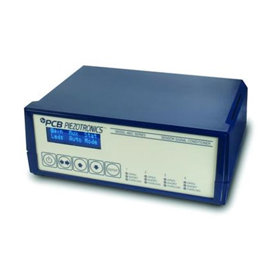
Page 12: 1-4.2 Quick Set-Up Instructions
1-4.2 Quick Set-up Instructions 1-4.2a Front Panel Introduction The following illustration shows the front panel module as it appears on model 482C27 when initially powered PCB 482C27 FW VER 1.0 This button is used to scroll DOWN through the options in the menus. - Page 13 MULTICHANNEL SIGNAL CONDITIONER MODEL 482C27 GENERAL OPERATION MANUAL GAIN SENS INPT FSOT FSIN FLTi A submenu will appear. Choose the channel you wish to change by using the up or down arrows. Once that is done use the left / right button to move the cursor over to the INPT column. To change the input, use either the up or down ...
- Page 14 MULTICHANNEL SIGNAL CONDITIONER MODEL 482C27 GENERAL OPERATION MANUAL 1-4.2c Directly setting the gain To enter the submenu for the incremental gain in the 482C27, place the cursor over the word GAIN in the main menu. This is shown as: GAIN...
-
Page 15: Operation: Standard Ac Line
Maintenance and Repair It is not recommended that the customer attempt to repair model 482C27 in the field. Should trouble occur, contact the factory for assistance. If the unit becomes dusty and dirty, it may be wiped off with a soft cloth. -
Page 16: Submenu Format And Command Selections
1) Gain Functionality – Includes five menu selections The following menu options all pertain to how the gain functionality operates in the 482C27. Gain Type (GType on front panel): Allows the user to choose how the gain of each channel can be set. The selections in the submenu are Gain and Normalize (Gain is the factory default setting). - Page 17 0010.0 The 482C27 has the ability to automatically normalize the output sensitivity of each channel based on the sensitivity of the sensor (SENS), the full scale value of the input (FSIN) in engineering units (g’s for example) and the full scale output (FSOT) of the amplifier expressed in volts (this is the output that a signal at an FSIN level will produce).
- Page 18 See section 1-4.2b. 3) Input Filter (FLTi on front panel): A screen stating ‘This Option is Not Installed’ will appear. The 482C27 does not come standard with an input filter, but the option is available. Contact the factory for more information.
- Page 19 02 mA The 482C27 will turn off the current excitation signal if the unit is not in ICP® input mode and will not allow it to be set while unless it is in ICP® mode. If a channel is selected from the EXCi menu that is inappropriate then NA will appear as shown below in place of the ICP®...
- Page 20 10.00 The 482C27 will turn off the voltage excitation signal if the unit is in ICP® or voltage input mode and will not allow it to be set while in those modes. If a channel is selected from the EXCv menu that is inappropriate then NA will appear as shown below in place of the voltage and polarity settings.
- Page 21 8) Auto Zero/ Auto Balance (ZERO on front panel): 482C27 includes an auto zero function for automatically zeroing channel outputs for any channel in DC coupling mode (zeroing works for any sensor input type). The auto balance function works for channels that are set to differential voltage, bridge (quarter, full, half), RSE and NRSE input modes ONLY (when DC coupling is enabled).
- Page 22 10) Switched Output (SWOT on front panel): Switched output capability is not applicable to the 482C27. A ‘This Option is Not Installed’ message will appear if it is selected.
- Page 23 MULTICHANNEL SIGNAL CONDITIONER MODEL 482C27 GENERAL OPERATION MANUAL 13) Channel Output Measurement (CHRD on front panel): The 482C27 is capable of digitizing the channel output and displaying it on the front panel. By moving the cursor upon the “CHRD” location, the display appears as follows:...
- Page 24 MULTICHANNEL SIGNAL CONDITIONER MODEL 482C27 GENERAL OPERATION MANUAL CHRD LEDS Ver? Unit Reset This screen will be displayed: Test CANCEL Use the up or down arrow keys to select ‘Execute’ or ‘Cancel’. Both options return control to the main menu. If ‘Execute’...
- Page 25 18) Reset to Factory Default Settings (Reset on front panel): The 482C27 reset capability provides a mechanism to reset the unit to its factory default settings. To do this select the ‘Reset’ option from the menu by placing the cursor over ‘Reset’ and hitting enter.
- Page 26 MULTICHANNEL SIGNAL CONDITIONER MODEL 482C27 GENERAL OPERATION MANUAL Display Opts Gain Following is what the screen will look like if the display was set to show ‘Gain’ and channel 1 has a gain of 2000 and is in full bridge mode with the input filter ‘On’ with no output filter option installed. Similarly, channel 2 has a gain of 10 and is in ICP®...
-
Page 27: Theory Of Operation
2 to 20 mA (current can be fixed or variable depending on the signal conditioner model). Sensor excitation occurs as the constant current of all channels are set. Model 482C27 allows the constant current to be adjusted between 1 and 20 mA to provide the required excitation for most applications. Special situations, such as driving extra-long cables (more than 1000 ft) with high frequency or fast rise time pulses, may require increasing the drive current to 12 mA or higher. -
Page 28: Input Protection
Input Fault Detection Model 482C27 monitors two input fault conditions, “short” and “open,” which indicate problems with sensor input and is displayed through the front panel LEDs. Either case implies that the sensor is NOT functioning properly. An input is shorted when it has a ground path for the sensor excitation and open when the sensor fails to draw the excitation. -
Page 29: Auto Scaling And Overload Detection
3-6.1 Auto Scale To avoid overload, model 482C27 features auto scaling for automatic gain adjustment (appears as ARNG on front panel display). It first sets maximum gain on all channels, then decreases the gain setting of any channel on which an overload has occurred. -
Page 30: Connector Configuration
3-7. Connector Configuration 482C27 provides BNC jack inputs for ICP sensors or voltage inputs and an 8 pin DIN connector NRSE, RSE, differential voltage and bridge (quarter, half, full) mode sensor inputs. The output connector is a BNC jack. 3-8. -
Page 31: Computer Interface Programming Guide
4-0. COMPUTER INTERFACE PROGRAMMING GUIDE 4-1. Introduction The RS-232 interface enables model 482C27 to be remotely controlled. With this interface, the unit is able to become part of a fully automated system. 4-2. RS-232 The RS-232 provides total control of the unit except for hardware RESET. The rest of the options described previously are computer controllable. - Page 32 MULTICHANNEL SIGNAL CONDITIONER MODEL 482C27 GENERAL OPERATION MANUAL After the DeviceInstaller application is installed, run it and the following screen will appear. Click on the Search icon and the program will search for the Ethernet device internal to the 482 unit. When found, as shown below, details about the device show in the list.
- Page 33 MULTICHANNEL SIGNAL CONDITIONER MODEL 482C27 GENERAL OPERATION MANUAL Important Note: The communication protocol requires a unit id as part of the command header. The unit id is not the IP address. To send commands to the unit via Ethernet you must address the TCP-IP packets with the proper IP address and ensure the packet payload contains the correct Unit Id in the command header.
- Page 34 MULTICHANNEL SIGNAL CONDITIONER MODEL 482C27 GENERAL OPERATION MANUAL After the Login dialog the Settings pane will appear on the left as shown below, click on Connection. Make sure the parameters are set as shown. If you need to change the Port # do it here.
- Page 35 MULTICHANNEL SIGNAL CONDITIONER MODEL 482C27 GENERAL OPERATION MANUAL...
- Page 36 MULTICHANNEL SIGNAL CONDITIONER MODEL 482C27 GENERAL OPERATION MANUAL...
- Page 37 MULTICHANNEL SIGNAL CONDITIONER MODEL 482C27 GENERAL OPERATION MANUAL...
-
Page 38: Model 482C27 Communication Guidelines
Command Summary The table below is a summary of the 482C27 command set. The 482C series is highly differentiated and some commands may not be valid in all units. The 482C commands are sent and received from/to the host computer in ASCII text format. -
Page 39: Command Format
FCN – The command invokes a function in the unit. 4-9. Command Format The 482C27 communication protocol incorporates the concept of 'Directed' and 'Global' commands at both the Unit and Channel level with the following characteristics; Unit or Channel numbers =0 are global commands that affect either all units or all channels of a particular unit or both. -
Page 40: 4-10. Commands
MULTICHANNEL SIGNAL CONDITIONER MODEL 482C27 GENERAL OPERATION MANUAL 4-10. Commands GAIN SET GAIN: This command sets the gain of a channel. Setting: The amplifier gain can be set directly by sending a Gain command: 1:0:GAIN=100.2\r\n (unit 1,all channels gain set to 100.2) When a channels gain is set directly the unit will adjust the FSI parameter of the gain equation using the following equation;... -
Page 41: Fsco
The INPT command sets the input mode for a given channel. The mode selection is sent as an integer value. All possible input modes for the 482/483 family are listed below. The bold items are valid input settings for the 482C27 and 483C28. -
Page 42: Iexc
MULTICHANNEL SIGNAL CONDITIONER MODEL 482C27 GENERAL OPERATION MANUAL ¼ Bridge ½ Bridge Full Bridge Referenced Single Ended 13 Differential Voltage 14 (same hardware settings as full bridge) Setting: 1:1:INPT= 12\r\n (unit 1, channel 1 input mode set to Full Bridge) -
Page 43: Fltr
MULTICHANNEL SIGNAL CONDITIONER MODEL 482C27 GENERAL OPERATION MANUAL 1:1:VEXC= -10.00 \r\n (unit 1, channel 1, sets minus (-) Bridge Excitation and plus (+)Bridge Excitation to 10.0 volts) 1:1:VEXC= 10.0 0\r\n (unit 1, channel 1, sets minus (-) Bridge Excitation to 0 and plus (+)Bridge Excitation to 10.0 volts) -
Page 44: Clmp
MULTICHANNEL SIGNAL CONDITIONER MODEL 482C27 GENERAL OPERATION MANUAL Global Response: 1: OFLT:1=1;2=0;3=0;4=0; CLMP The CLMP command enables or disables the Clamp feature. When Clamp is disabled the channel is ‘Buffered’ The Clamp value is sent as an integer value of either 0 –Disable (buffered) or 1-Enable. -
Page 45: Calb
Response: 1:SWOT:1=4; CALB The Calibration mode (CALB) command selects the calibration setting. For the 482C27 the options are OFF, Internal Shunt + or Internal Shunt -. For other models External Cal and Internal Cal using internally generated 100Hz or 1kHz sine wave signals are available. -
Page 46: Allc
MULTICHANNEL SIGNAL CONDITIONER MODEL 482C27 GENERAL OPERATION MANUAL used to store the basic TEDS data and up to 40 bytes in ASCII Hex format (8 bytes of Application register content if it was burned and 32 bytes of the EEPROM content). -
Page 47: Stus
MULTICHANNEL SIGNAL CONDITIONER MODEL 482C27 GENERAL OPERATION MANUAL N/A – Command is Read only Query: This command is a global command and will return all channel A/D readings regardless of the channel id in the command. Query Format: Unit#:Ch#:CHRD? Response format: Unit#:Cmd:Ch#:=CH1 A/D;… CHn#:=CHn A/D;... -
Page 48: Unid
MULTICHANNEL SIGNAL CONDITIONER MODEL 482C27 GENERAL OPERATION MANUAL Unit Id: Number of Channels: Starting Channel Number Followed by the 5 option bytes: Gain Options OPT_GAIN_x1 0x01 Fixed x1 OPT_GAIN_x5 0x02 Fixed x5 OPT_GAIN_x10 0x04 Fixed x10 OPT_GAIN_VAR 0x08 Variable Fixed (x1,x10,x100) -
Page 49: Azzr
MULTICHANNEL SIGNAL CONDITIONER MODEL 482C27 GENERAL OPERATION MANUAL Query: This command can be sent as a query but its usefulness is marginal being as it is a directed command and as such it is necessary to include the Unit Id in the command and the response will simply validate the commands unit id parameter. -
Page 50: Autr
MULTICHANNEL SIGNAL CONDITIONER MODEL 482C27 GENERAL OPERATION MANUAL 2:0:RSET = 1\r\n ( unit 2, channel 0, RSET cmd, 1(TRUE) ) Setting Response: 2:RSET:ok Query: The factory Defaults are: Gain = 1.0 Sensitivity = 10.0 Full Scale Input = 1000.0 ... - Page 51 MULTICHANNEL SIGNAL CONDITIONER MODEL 482C27 GENERAL OPERATION MANUAL Setting Response: 2:SAVS:ok Query: Communication Responses Typically the unit will return <Unit>:<Cmd String>:OK when the command is successful. Errors are indicated with negative numbers. The unit may return one of the following: <Unit>:<Cmd String>:OK<CR>...
- Page 52 MULTICHANNEL SIGNAL CONDITIONER MODEL 482C27 GENERAL OPERATION MANUAL 5-0. Wiring Information Differential voltage and full bridge mode can be used to accept a differential voltage signal from any source. Two additional modes, RSE (referenced single ended) and NRSE (non-referenced single ended) accommodate voltage inputs, such as 3 wire sensors with a power connection, ground connection and voltage signal output.
- Page 53 MULTICHANNEL SIGNAL CONDITIONER MODEL 482C27 GENERAL OPERATION MANUAL full bridge sensor V EXC + V EXC - optional shunt resistor (external) SENSE - SENSE + R SHUNT SIG - SIG + Figure 7 Alternate Connections for Differential Voltage/Full Bridge Type Sensors (sense leads connected at the signal conditioner) 5-2.
- Page 54 MULTICHANNEL SIGNAL CONDITIONER MODEL 482C27 GENERAL OPERATION MANUAL 5-3. Quarter Bridge Mode V EXC + internal three quarter bridge completion SIG - V EXC + quarter optional V EXC - bridge shunt resistor sensor SENSE- (external) SENSE + R SHUNT...
- Page 55 Appendix A: Differential MEMS Sensor Setup Guide for Model 482C27 In order to setup model 482C27 for use with differential MEMS sensors (such as PCB® model series 3501, 3503, 3641, 3651, 3741 and 3991) apply the following settings through the front panel control keypad: 1) Input Mode Select (INPT on front panel): Set sensor input type to Differential Voltage.
- Page 56 Appendix B: Single Ended MEMS Sensor Setup Guide for Model 482C27 In order to setup model 482C27 for use with single-ended MEMS sensors (such as PCB® model series 3711 and 3713) apply the following settings through the front panel control keypad: 1) Input Mode Select (INPT on front panel): Set sensor input type to RSE.
- Page 57 Model Number Revision: D BRIDGE/DIFFERENTIAL, ICP®/VOLTAGE SENSOR SIGNAL CONDITIONER 482C27 ECN #: 39690 Performance ENGLISH OPTIONAL VERSIONS Channels Optional versions have identical specifications and accessories as listed for the standard model ICP®, Voltage, ICP®, Voltage, except where noted below. More than one option may be used.
Need help?
Do you have a question about the 482C27 and is the answer not in the manual?
Questions and answers