PCB Piezotronics 480E09 Installation And Operating Manual
Battery-powered icp signal conditioners
Hide thumbs
Also See for 480E09:
- Installation and operating manual (143 pages) ,
- Installation and operating manual (9 pages) ,
- Installation and operating manual (53 pages)
Table of Contents
Advertisement
Quick Links
Model 480E09
1-Channel, battery-powered, ICP® sensor signal conditioner, gain x1, x10, x100, 2mA, BNC
input/output connectors.
Installation and Operating Manual
For assistance with the operation of this product,
contact the PCB Piezotronics, Inc.
Toll-free: 716-684-0001
24-hour SensorLine: 716-684-0001
Fax: 716-684-0987
E-mail: info@pcb.com
Web: www.pcb.com
Advertisement
Table of Contents

Related Manuals for PCB Piezotronics 480E09


Summary of Contents for PCB Piezotronics 480E09
- Page 1 1-Channel, battery-powered, ICP® sensor signal conditioner, gain x1, x10, x100, 2mA, BNC input/output connectors. Installation and Operating Manual For assistance with the operation of this product, contact the PCB Piezotronics, Inc. Toll-free: 716-684-0001 24-hour SensorLine: 716-684-0001 Fax: 716-684-0987 E-mail: info@pcb.com...
- Page 2 Assistance is needed to safely operate equipment PCB Piezotronics is an ISO-9001 certified company whose Damage is visible or suspected calibration services are accredited by A2LA to ISO/IEC Equipment fails or malfunctions 17025, with full traceability to SI through N.I.S.T.
- Page 3 CAUTION Refers to hazards that could damage the instrument. NOTE Indicates tips, recommendations and important information. The notes simplify processes and contain additional information on particular operating steps. The following symbols may be found on the equipment described in this manual: This symbol on the unit indicates that high voltage may be present.
- Page 4 PCB工业监视和测量设备 - 中国RoHS2公布表 PCB Industrial Monitoring and Measuring Equipment - China RoHS 2 Disclosure Table 有害物质 镉 汞 铅 (Pb) 六价铬 (Cr(VI)) 多溴联苯 (PBB) 多溴二苯醚 (PBDE) 部件名称 (Hg) (Cd) 住房 PCB板 电气连接器 压电晶体 环氧 铁氟龙 电子 厚膜基板 电线 电缆 塑料 焊接...
- Page 5 Component Name Hazardous Substances Lead (Pb) Mercury (Hg) Cadmium (Cd) Chromium VI Polybrominated Polybrominated Compounds Biphenyls (PBB) Diphenyl Ethers (Cr(VI)) (PBDE) Housing PCB Board Electrical Connectors Piezoelectric Crystals Epoxy Teflon Electronics Thick Film Substrate Wires Cables Plastic Solder Copper Alloy/Brass This table is prepared in accordance with the provisions of SJ/T 11364.
- Page 6 Model 482C02 / 480E09 ® Battery-Powered ICP Signal Conditioners Operating Manual with Enclosed Warranty Information 3425 Walden Avenue, Depew, New York 14043-2495 Phone (716) 684-0003 Fax (716) 684-3823 Toll Free Line 1-800-828-8840 MANUAL NUMBER: 19175 MANUAL REVISION: A ECO: 50452...
-
Page 7: Table Of Contents
Table of Contents Introduction ........................page 3 Description ........................page 4 Operation .......................... page 5 Performance Limits ......................page 8 Battery Considerations ..................... page 8 Optional Power Connections .................... page 9 Warranty ......................... page 10 Calibration & Service ...................... page 10 Return Procedure ...................... -
Page 8: Introduction
Model 480C02 & model 480E09 are rugged, portable, power sources for ICP sensors. These models are nearly identical except model 480C02 is unity gain 1:1 only with no adjustment, while model 480E09 has the additional feature of 3-position gain adjustment (1/10/100). They are powered internally by three replaceable batteries and ®... -
Page 9: Description
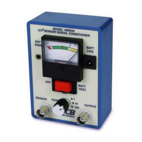
Figure 2: Model 480E09 Signal Conditioner Description Models 480C02 / 480E09 contain three, PP3 size, 9 volt batteries connected in series to provide DC power to internal electronics which provide regulation for approximately 2.6 mA of constant current power. Connections ®... -
Page 10: Operation
Some sensors use a 5 volt excitation and in this case the meter will read at the lower edge of the green region. 2.6 mA 480E09 Only Figure 3: Models 480C02 / 480E09 Signal Conditioner Schematic MANUAL NUMBER: 19175 MANUAL REVISION: A PAGE 5... - Page 11 If the sensor amplifier and/or cable are damaged to short open, the meter will indicate in the full scale (yellow) area. Should the sensor amplifier and/or cable be damaged to short closed, the meter will indicate zero volts (red area). Immediately after connecting readout instrument, (oscilloscope, meter, recorder, etc.) to the output jack, the 47 F coupling capacitor will begin charging through the internal resistor and input resistance of the readout instrument.
- Page 12 DC Coupling for Low-Frequency Response With the 480C02 / 480E09 connected as shown in Figure 5, the low frequency response of the coupling circuit is determined by the relationship in Equation 2. This requires use of a BNC Tee. Figure 6 below provides a comparison of AC vs DC coupling the same signal.
-
Page 13: Performance Limits
Performance Limits Output Voltage Limits Certain ICP sensors are capable of 10-volt output voltage swing. Models 480C02 / 480E09 with 27 volt supply will allow the positive-going side of the signal to go to +14 volts. The negative signal side is capable of -8 volts assuming a 10 volt turn-on for the sensor. -
Page 14: Optional Power Connections
Rechargeable Battery Use & Charging WARNING, models 480C02 / 480E09 do not ship with rechargeable batteries and PCB external battery chargers are suitable for use with Nickel-Cadmium (Ni-Cad) rechargeable batteries only. It should not be used with alkaline or other non-rechargeable batteries. -
Page 15: Warranty
Warranty PCB instrumentation is warranted against defective material and workmanship for 1 year unless otherwise expressly specified. Damage to instruments caused by incorrect power or misapplication, is not covered by warranty. If there are any questions regarding power, intended application, or general usage, please consult with your local sales contact or distributor. -
Page 16: Total Customer Satisfaction
Total Customer Satisfaction PCB, a division of PCB Piezotronics, guarantees Total Customer Satisfaction. If, at any time, for any reason, you are not completely satisfied with any PCB product, PCB will repair, replace, or exchange it at no charge. You may also choose, within the warranty period, to have your purchase price refunded. - Page 17 Model Number Revision: V BATTERY-POWERED SIGNAL CONDITIONER 480E09 ECN #: 45339 Performance ENGLISH OPTIONAL VERSIONS Channels Optional versions have identical specifications and accessories as listed for the standard Frequency Range(-5 %)(x1, x10 Gain) 0.15 to 100,000 Hz 0.15 to 100,000 Hz model except where noted below.
Need help?
Do you have a question about the 480E09 and is the answer not in the manual?
Questions and answers