Eastwood MIG175 WELDER Service Manual
Hide thumbs
Also See for MIG175 WELDER:
- Assembly and operating instructions manual (13 pages) ,
- Assembly & operating instructions (17 pages) ,
- Instructions (4 pages)
Advertisement
Advertisement
Table of Contents

Related Manuals for Eastwood MIG175 WELDER


Summary of Contents for Eastwood MIG175 WELDER
- Page 1 Item #12012 MIG175 WELDER SERVICE MANUAL...
-
Page 2: Specifications
This warranty is void if the equipment has been subjected to improper installation, improper care or abnormal operations. WARRANTY PERIOD: All warranty periods begin on the date of purchase from Eastwood. Warranty Periods are listed below, along with the products covered during those warranty periods: 3 Year Warranty on Material, Workmanship, and Defects: •... -
Page 3: Safety Information
• Always keep a fire extinguisher nearby while welding. • Use welding blankets to protect painted and or flammable surfaces; rubber weather-stripping, dash boards, engines, etc. • Ensure power supply has properly rated wiring to handle power usage. To order parts and supplies: 800.343.9353 >> eastwood.com... - Page 4 • Electric welding heats metal and tools to temperatures that will cause severe burns! • Use protective, heat resistant gloves and clothing when using Eastwood or any other welding equipment. Never touch welded work surface, torch tip or nozzle until they have completely cooled.
-
Page 5: Components And Controls
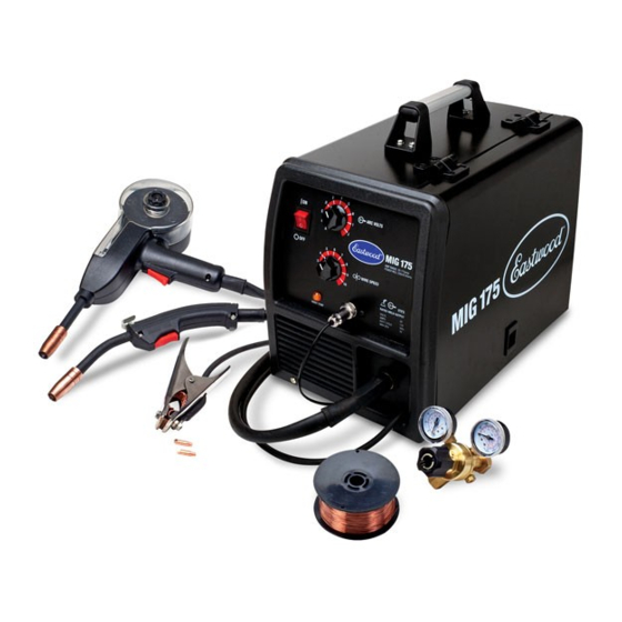
17. Wire Spindle 18. Contact Tip 19. Nozzle 20. Ground Clamp 21. Trigger Connections 22. Drive Roller 23. MIG Torch 24. Spool Gun 25. MIG Gun/Spool Gun Selector Switch 26. Regulator 19 18 To order parts and supplies: 800.343.9353 >> eastwood.com... -
Page 6: Installation
4. Reinstall the Black Ground Knob and fi nger tighten. CHANGING POLARITY The Eastwood MIG175 comes set up to weld with Solid Wire, to use a Flux Cored wire the Polarity must be changed. ELECTRIC SHOCK CAN CAUSE INJURY OR DEATH! Disconnect welder from power supply before beginning. - Page 7 • Use proper equipment, procedures and have adequate help when moving or lifting cylinders. A Shielding Gas Bottle is not included with your Eastwood MIG175 but is necessary to welding using Solid Wire. This can be bought at most local Welding Supply Stores.
- Page 8 INSTALLING WIRE SPOOL The Eastwood MIG175 can be used with either a 4”or an 8” Wire Spool. To use the larger 8” spool an included adaptor is necessary. To install a 4” Wire Spool: 1. Open the door of the welder and remove the wing nut (FIG. G2), spacer (FIG. G1), and 8” Spool Adaptor (FIG. G3) from the Wire Spool Spindle.
- Page 9 7. Tighten the star knob fi nger tight. 8. Push the rocker arm back down into place. 9. Lift up on the Tensioner to put back in place and adjust as necessary. To order parts and supplies: 800.343.9353 >> eastwood.com...
- Page 10 11. Plug in welder to your power source and turn on the welder. 12. Trigger the Spool Gun to feed the wire and adjust the Brass Tensioner Thumb Screw (FIG. K2) so that the wire does not slip. 13. Replace Contact Tip and Nozzle. FIG. K Eastwood Technical Assistance: 800.343.9353 >> tech@eastwood.com...
-
Page 11: Operation
• Electric welding heats metal and tools to temperatures that will cause severe burns! • Use protective, heat resistant gloves and clothing when using Eastwood or any other welding equipment. Never touch welded work surface, torch tip or nozzle until they have completely cooled... -
Page 12: Overload Protection
WELDING PROCESS Your Eastwood MIG175 can be used to form a large number of different joints and welds all of which will require practice and testing before using on an actual project piece. This following welding process is just a baseline to get you started. -
Page 13: Troubleshooting Table
Adjust Drive Roller pressure as Drive Roller pressure too low Check Drive Roller pressure needed Confirm correct drive roller for Replace with correct drive roller Incorrect Drive Roller wire size if needed To order parts and supplies: 800.343.9353 >> eastwood.com... - Page 14 Board and pin 1 on CON 3. With torch trigger pulled, check If voltage present, Replace Faulty Transformer or Rectifier voltage across pin 2 on CON 1 Welder and pin 1 on CON 3. Eastwood Technical Assistance: 800.343.9353 >> tech@eastwood.com...
- Page 15 Output Voltage (24V - 30V DC across Voltage Potentiometer Range) Disconnect plug Con 10 and check for continuity through temp switch (R = 0 Ohms) Resistance of potentiometers – 0 to 10 kOhms To order parts and supplies: 800.343.9353 >> eastwood.com...
- Page 16 EXPLODED VIEW WITH PARTS LIST Eastwood Technical Assistance: 800.343.9353 >> tech@eastwood.com...
- Page 17 Main Control Board Support Not Available Main Control Board (Old Style – Model with Plastic MIG Gun Connector) 22535 Main Control Board (Discrete Board Components) 33109 Main Control Board (Surface Mount Board Components) To order parts and supplies: 800.343.9353 >> eastwood.com...
- Page 18 NOTES Eastwood Technical Assistance: 800.343.9353 >> tech@eastwood.com...
- Page 19 NOTES To order parts and supplies: 800.343.9353 >> eastwood.com...
- Page 20 See our complete line of consumables and parts at www.eastwood.com If you have any questions about the use of this product, please contact The Eastwood Technical Assistance Service Department: 800.343.9353 >> email: tech@eastwood.com The Eastwood Company 263 Shoemaker Road, Pottstown, PA 19464, USA 800.343.9353 eastwood.com...
Need help?
Do you have a question about the MIG175 WELDER and is the answer not in the manual?
Questions and answers