Advertisement
Quick Links
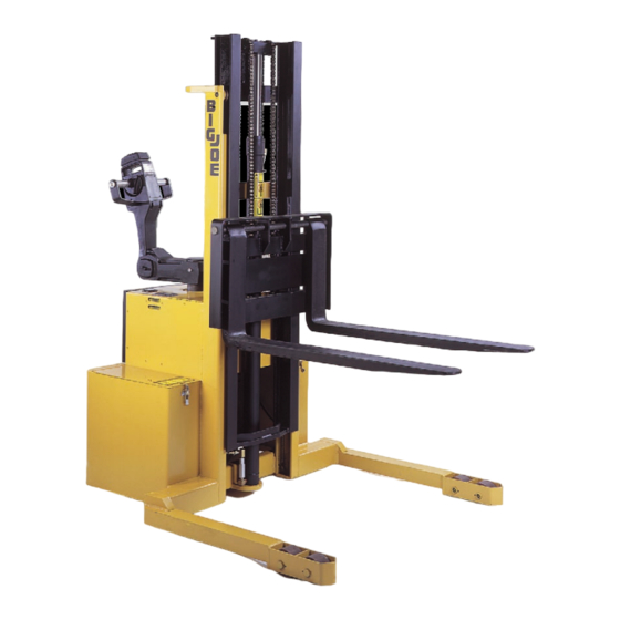
TRUCK MODEL
PDM Equipped With Special Features
1. GENERAL
This document supplements the basic PDM Manual
No. 901356 and provides additional operating, safety
and maintenance information.
Ultra-deep discharging of brand new batteries should be avoided for at least 15 cycles.
These batteries have a superior deep cycle life. However, to dramatically extend battery life, ultra-deep
discharge should be avoided. The shallower the average discharge, the longer the life.
If the batteries are continually undercharged, performance is reduced and life is shortened.
THESE BATTERIES ARE MAINTENANCE-FREE. ANY ATTEMPT TO OPEN THE BAT-
TERY WILL VOID WARRANTY.
Document 367
06/12/06
SUPPLEMENT
CIRCUIT CITY
PDM-20-154
Table 1. Serial Number Effectivity
375784 AND HIGHER
Additional standard equipment of the platform, strobe
light, a lowering buzzer, an emergency lowering valve,
a keyswitch, an emergency power disconnect (EPD),
a safety belt, and a self-retracting lifeline.
IMPORTANT
SERIAL NUMBERS
PDM
1
Advertisement

Subscribe to Our Youtube Channel
Related Manuals for BigJoe PDM-20-154

Summary of Contents for BigJoe PDM-20-154
- Page 1 SUPPLEMENT CIRCUIT CITY PDM-20-154 Table 1. Serial Number Effectivity TRUCK MODEL SERIAL NUMBERS PDM Equipped With Special Features 375784 AND HIGHER 1. GENERAL Additional standard equipment of the platform, strobe light, a lowering buzzer, an emergency lowering valve, This document supplements the basic PDM Manual a keyswitch, an emergency power disconnect (EPD), No.
-
Page 2: Safety Precautions
2. SAFETY PRECAUTIONS • Lower platform to floor level for personnel to enter and exit. Do not climb on any part of the truck in The following safety precautions must be adhered to attempting to enter and exit. at all times. •... - Page 3 R6287 Figure 1. Location of Special Items INDEX PART PART NAME INDEX PART PART NAME REQ. REQ. — HYDRAULIC SYSTEM 054412 CASTER (FIGURE 003216 BATTERY — EPD CONTACTOR BOX — BATTERY CHARGER (FIGURE (FIGURE 20574 DECAL — ELECTRICAL PANEL ASSEMBLY 020698 SWITCH, EPD ENGAGE (FIGURE...
- Page 4 4.1. Safety Check WARNING: Exceeding the load rating specified above can cause the truck to tip resulting The following safety checks should be made at least in possible injury. once each day to verify operation of safety devices. Also perform the daily checks in the basic PDM Man- 4.3.
-
Page 5: Planned Maintenance
5. PLANNED MAINTENANCE Refer to the basic PDM Manual No. 901356 Chapter 3 for basic planned maintenance procedures. Table 2 indicates additional planned maintenance tasks which should be performed on a quarterly basis. These maintenance procedures should be performed only by qualified service personnel. -
Page 6: Maintenance
6. MAINTENANCE and charging. After the batteries charge to approximately 80% the Yellow LED comes Refer to the basic PDM Manual No. 901356 for all ON. After a time (1 hour minimum) the Green general service information. Refer to Figure 1 for the LED comes ON indicating battery ready. - Page 7 6.1.2. Removing Batteries from Charger 6.2. Electrical System Refer to the basic PDM Manual No. 901356 for all 1. The Green “READY“ LED stays on until the general service information. Refer to Supplements 220 charger is unplugged from AC outlet. for general information for the Steering Control Head.
- Page 8 6.3. Battery Charger The 23840 battery charger is located inside the cover in front of the steering arm as shown in Figure 1. Refer Figure 3 for charger installation and Figure 4 for dis- assembly and part number information. R6286 Figure 3.
- Page 9 R6288 Figure 4. Battery Charger INDEX PART PART NAME INDEX PART PART NAME REQ. REQ. 904075 . . PCB ASSY WITH HEATSINK — 23840 CHARGER, 24 VOLT 904074 . . . THERMISTOR 056681 . DECAL, CHARGER, LED 003403 . . CIRCUIT BREAKER, AUTO RESET 023018 .
- Page 10 6.4. Battery Charger Troubleshooting a. Verify 25 VAC from blue wire to each white wire. Refer to Figure 6 for part identification. Be sure the batteries are connected to the charger and the AC b. Verify 50 VAC from the white wire to white cord is connected to 120 VAC power supply.
- Page 11 NOTES Document 367...
- Page 12 R6289A Figure 6. Wiring Diagram (Sheet 1) Document 367...
- Page 13 R6289B Figure 6. Wiring Diagram (Sheet 2) Document 367...
- Page 14 6.5. Electrical Control Panel The 23836 electrical control panel is located inside the cover below the steering arm as shown in Figure Refer to Figure 7 for disassembly and part number information. R6290 Figure 7. Electrical Panel Assy. Document 367...
- Page 15 INDEX PART PART NAME INDEX PART PART NAME REQ. REQ. 504150-01 . CABLE ASSY - A2 — 23836 PANEL ASSY-ELECT, TRANSISTOR 505084-14 . CABLE ASSY - POS 506044 . PANEL WELDMENT 505181-50 . CABLE ASSY - NEG 008904 . FUSEHOLDER 063552 .
- Page 16 6.6. Flashing Red Light Refer to Figure 8 Figure 9 for part number and wir- ing information. The Flashing Red Light is located on the Mast as shown in Figure R6291 Figure 8. Flashing Light Wiring Diagram INDEX PART PART NAME INDEX PART PART NAME...
- Page 17 R6292 Figure 9. Flashing Red Light, Remote Control Conduit and EPD Reset Button INDEX PART PART NAME INDEX PART PART NAME REQ. REQ. 077207 WASHER 005318 ELBOW 056122 CLIP 023014 WIRE BUNDLE 071376 SCREW 005311 CONDUIT 077031 WASHER 005317 CONNECTOR —...
- Page 18 6.7. Platform Remote Control Box Refer to Figure 9 Figure 10 for part number and wiring information. The Remote Control UP DOWN STOP push-button switch box assy 11151 is located on the Platform as shown in Figure R6294 Figure 10. Remote Control Box INDEX PART PART NAME...
- Page 19 6.8. Platform Buzzer The platform lowering buzzer housing is located near the front lower edge of the platform as shown in Figure 1. Refer to Figure 10 Figure 11 for part number information. R6293 Figure 11. Buzzer and Housing INDEX PART PART NAME INDEX...
- Page 20 6.8.1. Spike Suppressor & Diode Assy The 505837 suppressor and diode assembly is located on remote lowering valve solenoid which is mounted on the bottom of the hydraulic pump as shown in Figure R6295 Figure 12. Spike Suppressor & Diode Assys. INDEX PART PART NAME...
- Page 21 6.9. EPD Contactor Box The EPD Contactor Box is located in the left side of the transmission compartment as shown in Figure Refer to Figure 13 for disassembly and part number information for the EPD Contactor Box. INDEX PART PART NAME REQ.
- Page 22 6.10. Hydraulic System Refer to Figure 15 For disassembly and part number information for the hydraulic panel assembly. Refer to Figure 14 For disassembly and part number information for the complete hydraulic system. Refer to Figure 16 For disassembly and part number information for the lift cylinder.
- Page 23 R6298 Figure 15. Hydraulic Panel Assembly INDEX PART PART NAME INDEX PART PART NAME REQ. REQ. 026302 . PLUG, DRAIN, MAGNET, 3/8 — 23832 PANEL ASSEMBLY, HYDRAULIC ° 025540 . ADAPTER, 90 ELBOW 500690 . PANEL WELDMENT 026109 . NIPPLE, 3/8” 506237 .
- Page 24 PACKING KIT PART NUMBER 900142 CONTAINS: ITEM R6106 Figure 16. Lift Cylinder INDEX PART PART NAME INDEX PART PART NAME REQ. REQ. — . NOT USED — 9826-31 LIFT CYLINDER ASSY — . NOT USED — . TUBE ASSY — .NOT USED 049509* .
- Page 25 6.11. Elevation System Refer to Figure 17 For disassembly and part number information for the complete elevation system. R6299 Figure 17. Elevation System INDEX PART PART NAME INDEX PART PART NAME REQ. REQ. 403951 SHIM, BLOCK, STOP 402055 CLEVIS PIN, 0.200 DIA. X 1 403952 BLOCK, STOP 402034...
- Page 26 6.12. Platform The complete platform 506268 is shown in Figure Refer to Figure 17 For disassembly and part number information for the boom and grab handle compo- nents. R6300 Figure 18. Boom and Grab Handle Components INDEX PART PART NAME INDEX PART PART NAME...
- Page 27 Document 367...
- Page 28 Big Joe Manufacturing Company Document 367...
Need help?
Do you have a question about the PDM-20-154 and is the answer not in the manual?
Questions and answers