Table of Contents
Advertisement
Quick Links
Advertisement
Table of Contents

Subscribe to Our Youtube Channel
Related Manuals for Datum 4040B


Summary of Contents for Datum 4040B
- Page 1 4040B Caesium Time & Frequency Standard...
- Page 3 The equipment or software described in this manual have been developed solely at the expense of Datum - TT&M and are proprietary. No unlimited rights in technical data are granted. Limited rights as per DFARS 252.227-7013 shall be effective for 10 years from the copyright date.
-
Page 4: Table Of Contents
CHAPTER ONE Introduction/Product Overview Instrument Identification About This Manual Typographical and Other Conventions Instrument Identification CHAPTER TWO Installation Environment Mounting Electrical Connections External DC Connections Unit Certifications Preparation for Shipment CHAPTER THREE Operation Turn-On Procedure Operational Check Connections to RS232 Interface Start-Up Phase Turn-On Without PC PC-Assisted Turn-On... - Page 5 CHAPTER FOUR Remote Control Software Monitor.exe Software Setting Up the Serial Link Operating Instructions Parameters Alarms Minor Alarm Messages Major Alarm Messages: (without tube shutdown) Major Alarm Messages: (resulting in tube shutdown) Graphic Display Miscellaneous Functions Format of ASCII Strings Transmitted & Received at the PC Remote Control On Remote Control Off Request Variables Data Message...
-
Page 7: Chapter One
The Datum 4040B CaesiumTime and Frequency Standard is a primary frequency and time reference with microprocessor control. The major function of the Datum 4040B is to produce accurate, stable, and spectrally pure sinusoidal signals, and precise timing signals. To accomplish this, a caesiumbeam tube resonator is used to stabilize the output of a quartz crystal oscillator. -
Page 8: About This Manual
• Chapter One – Introduction/Product Overview: This chapter includes an overview of this Operating Manual, the intended audience, and the stylistic and typographical conventions used. • Chapter Two – Installing the Datum 4040B: Describes initial inspection of the 4040B, preparation for use, and signal interconnections. -
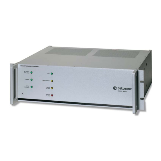
Page 9: Instrument Identification
INSTRUMENT IDENTIFICATION A slash (/) and a three-digit number, following the four-digit model number (4040B) specifies an option that is supplied within the instrument. See Chapter Five for a list of available options. Chapter Six pro-... - Page 10 WARNINGS, CAUTIONS, RECOMMENDATIONS, AND NOTES Warnings, Cautions, Recommendations, and Notes attract attention to essential or critical information in this Operating Manual. The types of information included in each are explained as follows: WARNING … All warnings have this symbol. Do not disregard warnings. They are installation, operation, or maintenance procedures, practices, or statements that if not strictly observed, may result in personal injury or loss of life.
- Page 11 Fax: +1-978-927-4099 E-mail: ttmsales@datum.com Thank you for providing the information. NOTE … Datum offers a number of applicable training courses designed to enhance product usability. Contact your Datum representative or sales office for a complete list of courses and outlines.
-
Page 12: Chapter Two
0 or 3.625 inches behind the Datum 4040B front panel. ELECTRICAL CONNECTIONS The Datum 4040B may be powered from an external AC source, 115 or 230 VAC. The instrument may also be powered by an external DC source (22 to 56 V). Before connecting power, check to see that... -
Page 13: External Dc Connections
AC and DC power connectors. EXTERNAL DC CONNECTIONS The Datum 4040B employs an internal DC-DC converter to provide a wide input voltage range as well as electrical isolation between the DC input and chassis ground. Either side of the DC input may be at chassis ground potential. - Page 14 FIGURE 2-1. DATUM 4040B INTERFACE CONTROL DRAWING...
-
Page 15: Preparation For Shipment
PREPARATION FOR SHIPMENT In the event that the Datum 4040B must be shipped to a new operating location, or returned to the fac- tory for service, proper care must be taken in preparation for shipment and packing to ensure that the product is not damaged in transit. - Page 16 United Parcel Service and Federal Express are examples for the United States. Intercontinental (617-569-4400) provides international shipping services. Contact one of these shipping companies for assistance. If you need additional help, call Datum Shipping Department. The following information is typically requested:...
- Page 17 FIGURE 2-2. PLACEMENT OF LABELS...
-
Page 18: Chapter Three
Datum 4040B CaesiumFrequency Standard. TURN-ON PROCEDURE Except for the application of power, no specific user actions are required to turn-on the Datum 4040B and obtain the specified rf output signals. Application of either AC or DC power initiates the warm-up and automatic lock acquisition sequence. -
Page 19: Operational Check
TABLE 3-1. MONITORS AND INDICATORS OPERATIONAL CHECK After the Datum 4040B has been operating for its specified warm-up time, it can be examined to verify proper operation: If another reference standard of known accuracy is available, a measurement of the Datum 4040B fre- quency offset can be made. -
Page 20: Connections To Rs232 Interface
The start-up phase ends as soon as one of the following conditions is met: a) Oscillator warm and stabilized caesium oven. b) 45 minutes after switching on the unit. NOTE . . . If the Datum 4040B has been in storage for an extended period, the warm-up time may be greater than specified. -
Page 21: Turn-On Without Pc
For a more total control, it is best to connect the unit to a PC. NOTE . . . The Datum 4040B unit is set for 2400 Baud, 7 data, 2 stop, odd parity. • Start the MONITOR.EXE program (Appendix A gives a detailed description of the MONITOR.EXE program). -
Page 22: Pps Output
FIGURE 3-2. MODULE LAYOUT 1 PPS OUTPUT A block diagram of the 1 PPS circuit is shown below in Figure 3-3. A 10 MHz TTL signal from the RF Output Assembly drives a divide-by-107 counter to produce a 1 PPS, 20 µsec wide timing pulse. - Page 23 FIGURE 3-3. BLOCK DIAGRAM FIGURE 3-4. DATUM 4040B 1 PPS OUT AND 1 PPS SYNC CONNECTOR LOCATIONS (REAR PANEL) FIGURE 3-5. 1 PPS SYNC FUNCTION...
-
Page 24: Chapter Four
A sample program is available (upon request to marketing/sales) which demonstrates the uses of the RS232 interface for monitoring and control of the Datum 4040B. The software processes and displays the operating parameters of the instrument, including data file creation, and real-time or off-line graphic display of data. -
Page 25: Setting Up The Serial Link
SETTING-UP THE SERIAL LINK Connect the Datum 4040B to the PC with a null modem cable. The 4040B is defined as DTE. The 4040B only uses CTS as a control line input and it provides RTS and DTR as control line outputs. -
Page 26: Operating Instructions
OPERATING INSTRUCTIONS After turn-on, the screen displays 2 windows with the following parameters and alarms: The upper line displays a reminder of the commands triggered by the function keys <F1> to <F10>. -
Page 27: Parameters
PARAMETERS Rate : Shows sampling rate and countdown time to next acquisition. This parameter can be modified using <F7> (serial input rate). (The sampling rate must be compatible with the PC speed and the number of connected units when data is saved on the disk). Sampling rates which are too short will not allow sufficient time for data acquisition and disk storage. - Page 28 • <F8> (Unit selection) opens a window which lists the connected units. Allows modification of this list and selection of the unit under control. CAUTION . . . Only the connected units may be included in this list. Thus the serial number of disconnected units must be set equal to zero. To select the unit under control, position the pointer opposite the chosen unit serial number by means of the <UP>...
- Page 29 If a .CFM file was selected for input, the next window offers selection of the reading mode for the selected data file. Read one line of 1: reads each line of the data file Read one line of N: read every on Nth line which changes the graphic display scale (for instance, read one line of 4 to enlarge the time span of the scale displayed by 4-fold.) In the "read"...
- Page 30 The new values are transmitted by <ENTER>. The _ sign appears when the reset is performed with the <ENTER> key. • CTRL <F1> is not used by the Datum 4040B module. • ALT <F1> is not used by the Datum 4040B module.
-
Page 31: Alarms
ALARMS The message in the window center provides information about the state of the unit. The variable string acquired from the RS232 port contains a substring as such: "ALM:SS (nn,nn,nn,nn,nn)" where: ss is a two digit status string and nn is a two digit alarm number. The alarm states and messages below have their associated numbers to illustrate the alarms report- ing structure. -
Page 32: Major Alarm Messages: (Resulting In Tube Shutdown)
MAJOR ALARM MESSAGES: (RESULTING IN TUBE SHUTDOWN): Excess oven heating > 10V/45 min Excess OCXO heating Hot-Wire volt error >± 0.16V Ion-Pump current > 240 µA 24V Supply voltage <20V >30V Reset the alarms <F1> after correcting the error. GRAPHIC DISPLAY •... -
Page 33: Graphic Display
• <F2> (Graphic display). The parameters chosen above are graphically displayed. The horizontal scale is given in the last line. An example is shown in Figure A3.3. S = X total scale C = X center offset These scales can be modified using <F4>. The Y time scale is given in min/div. and depends on the sampling rate at the time of filing (see F5). -
Page 34: Miscellaneous Functions
MISCELLANEOUS FUNCTIONS <Q> key Quits program to D.O.S. <R> key Resets graphic spooler. (The spooler is a section of memory which stores one screenful of selected graphical data. Re-setting the spooler permits the over writing of this section of memory with incoming real time data). <S>... -
Page 35: Format Of Ascii Strings Transmitted & Received At The Pc
When not using the Datum MONITOR.EXE software application, it is possible to directly send and receive information from the instrument. Communicating with the 4040B directly through a computer's serial port is accomplished using a vari- ety of ASCII character sequences. The formats of these sequences are described below. -
Page 36: Request Variables Data Message
Format: [STX]D*1_nnnnn_[ETX] NOTE . . . nnnnn represents the 5-digit serial number of the 4040B. In response to this command the 4040B will return a string of 338 characters (including control characters). Each variable is positioned in the string according to Table 4-1. -
Page 37: Request Constants Data Message
NOTE . . . nnnnn represents the 5-digit serial number of the 4040B. In response to this command the 4040B will return a string of 145 characters including control charac- ters). Each variable is positioned in the string according to Table 4-2. -
Page 38: Remote Control Commands
REMOTE CONTROL COMMANDS General Format: [STX]Wdd_nnnnn_ccccccccc[ETX] NOTES . . . • nnnnn represents the 5-digit serial number of the 4040B. • ccccccccc represents the 9-character data field. Unless otherwise noted c designates a don't care value. • dd represents the 2-digit function code for the commands specified in Table 4-3. -
Page 39: Chapter Five
-80 dBc -80 dBc Warm-Up Time* 30 minutes 1 100% verified and calibrated against Datum in-house standard. * If the Datum 4040B has been in storage for an extended period, the warm-up time may be greater than specified. **Excluding environmental effects. -
Page 40: Outputs
OUTPUTS Sinusoidal Output Rear Panel (standard 1 ea.) 1, 5, 10 MHz (one each on rear panel) Amplitude 1.0 Vrms into a 50_ load TTL Output Rear Panel .1, 1, 5. 10 MHz (user selectable) 1.544 MB/s, Option 063 2.048 MB/s, Option 064 Balanced Outputs Rear Panel 1.544 MHz, balanced DS1, Option 063... -
Page 41: Environment
Fuses AC Line Input @ 110 VAC T2 A, 5 mm x 20 mm AC Line Input @ 220 VAC T0.8 A, 5 mm x 20 mm Ext DC Input F3.15 A, 5 mm x 20 mm for Europe Ext DC Input F3.0 A FB, 5 mm x 20 mm for US Dimensions (maximum) Height... - Page 42 FIGURE 5-1. FREQUENCY STABILITY (5 second time constant, 2nd order loop) FIGURE 5-2. SINGLE SIDE-BAND PHASE NOISE SPECTRAL DENSITY (1 second time constant, 2nd order loop)
-
Page 43: Options
1.544 MHz TTL and Balanced DS1 Outputs (Option 063) The Datum 4040B can be configured with an internal 1.544 MHz synthesizer. This signal displays the same accuracy and frequency stability as the standard Datum 4040B RF outputs. Option 063 cannot be combined with Option 064. -
Page 44: Monitor Pin-Out
MONITOR PIN-OUT The Datum 4040B is equipped with a fifteen Pin-D connector which allows the user to access the relay contacts of various alarm conditions (described in Table 5-2). FIGURE 5-3. MONITOR CONNECTOR (J11 REAR PANEL) TABLE 5-2. MONITOR CONNECTOR PINOUTS NOTE . - Page 45 FIGURE 5-4. DATUM 4040B (SIDE PANEL AND TOP VIEW)
- Page 46 FIGURE 5-5. DATUM 4040B FRONT PANEL FIGURE 5-6. DATUM 4040B REAR PANEL...
-
Page 47: Storage/Shelf Life
STORAGE/SHELF LIFE, DATUM 4040B During storage of the Datum 4040B, there are two factors to consider; caesium beam tube vacuum and shelf life. Caesium Beam Tube Vacuum and Standby Operation If extended periods of storage is anticipated, the ion pump in the Caesium Beam Tube must be operat- ed to maintain tube vacuum. -
Page 48: Chapter Six
Option 063 adds a DS1 Telecommunications Synthesizer PCB Assembly, A2, to the Datum 4040B. With Option 063, the Datum 4040B can serve as a stand alone Stratum 1 Master Clock or as a component of a master clock system. Option 063 adds the following outputs to the rear panel of the instrument: •... - Page 49 This input allows the DS1 and Frame Alignment output signals to be synchronized to an external refer- ence. A contact closure summary alarm is added to the rear panel MONITOR connector. The specifications for Option 063 are provided on the following page, and are added to the specifica- tions for the Datum 4040B in Chapter Five.
-
Page 50: Option 063 Specifications
OPTION 063 SPECIFICATIONS, DS1 SYNTHESIZER OUTPUTS Signal Type DS1, balanced Frequency 1.544 MHz Format Framed all 1's (D4 or ESF) Jitter <0.05 U.I. Connectors (connected in parallel) Twin - BNC, receptacle (31-223, Amphenol) Mating Connector (31-224, Amphenol) WECO type receptacle (MT-332B, Switchcraft) Mating Connector (483, Switchcraft) Bantam type receptacle (TT-32BDC, Switchcraft) Mating Connector (TT253, Switchcraft) -
Page 51: Operation
OPERATION Connections All Option 063 external connections are made at the Datum 4040B rear panel. The TTL CLOCK output uses BNC connectors. The DS1 signal is presented on the rear panel connectors J1, J2 and J3. (Note: These connectors are connected in parallel). - Page 52 If the caesium module is operational and the fault exists only with the DS1 Synthesizer Assembly, the Datum 4040B front panel LOCK indicator is lit. When the OP ALARM indicator is lit and the LOCK indi- cator is not lit, the problem is most likely related to the caesium module.
-
Page 53: Theory Of Operation
THEORY OF OPERATION Functional Description The DS1 Synthesizer consists of: · A Digital Phase-locked Synthesizer · DS1 Format Generator and Synchronization Circuit · Frame Detector Circuit · Alarm Circuitry · Power Converter Refer to Figure 6-063-2 for a block diagram of the DS1 Synthesizer Assembly. Digital Synthesizer The digital synthesizer section phase-locks a 6.176 MHz VCXO to a 10 MHz reference signal that is supplied by the Caesium Frequency Module, A1. - Page 54 Frame Marker output pulse. Alarm Circuitry Alarm circuitry is provided by relay contacts that are brought to the Datum 4040B's rear panel MONI- TOR connector. The relay is activated by a loss of the 10 MHz reference input signal, a loss of the 6.176 MHz phase-lock, a loss of Caesium lock, or a failure of the DS1 driver circuit.
-
Page 55: Option 064 - Cept Frequency Synthesizer
OPTION DESCRIPTION Option 064 adds a CEPT Telecommunications Synthesizer PCB Assembly to the DATUM 4040B. With Option 064, the DATUM 4040B can serve as a Stratum 1 Master Clock or as a component of a master clock system. Option 064 adds the following outputs to the rear panel of the instrument: •... - Page 56 Note that no bal- anced output is present during DATUM 4040B warm-up and lock acquisition. A Frame Detector circuit determines the start of each frame and provides a Frame Marker output pulse with each occurrence.
- Page 57 FIGURE 6-064-2. CEPT SYNTHESIZER ASSEMBLY BLOCK DIAGRAM...
-
Page 58: Option 064 Specifications
OPTION 064 SPECIFICATIONS, CEPT SYNTHESIZER OUTPUTS CEPT Signal Type CEPT, balanced Frequency 2.048 MHz Format Framed all 1's Jitter <0.05 U.I. Connector Balanced 120W, Twin-BNC receptacle (31-223, Amphenol) Mating connector (31-224) Unbalanced 75W, BNC Frame Marker Signal Type Frequency 8 kHz Connector TTL clock Signal Type... -
Page 59: Installation
To synchronize, briefly apply the reference signal to the rear panel BNC connector labeled 8 KHZ. Another DATUM 4040B/064 may be used as a reference by connecting its CLOCK output to the SYNC input to the unit being synchronized. Synchronization occurs on the next clock pulse after the SYNC input has returned to a logic "1". - Page 60 Loss of Signal A CEPT signal loss can be caused by: • Loss of internal 10 MHz reference input signal to the assembly, • Loss of CEPT Synthesizer phase-lock, or • Loss of the caesiumlock (or before the unit has achieved lock during warm-up). If the caesiummodule is operational and the fault exists only with the CEPT Synthesizer Assembly, the front panel LOCK indicator is lit.
- Page 61 - TT&M guarantees its products to be free from defects in material and workmanship for a period of one year from the date of shipment. Datum - TT&M shall, at its option, either repair or replace hardware products which prove to be defective.
Need help?
Do you have a question about the 4040B and is the answer not in the manual?
Questions and answers