Fox Thermal FT1 Troubleshooting Manual
Flow meter
Hide thumbs
Also See for FT1:
- Manual (106 pages) ,
- Troubleshooting manual (2 pages) ,
- Instruction manual (110 pages)
Advertisement
Quick Links
Fox Thermal Flow Meter Troubleshooting Guide
Introduction
This document is used to address troubleshooting, installation, and calibration issues on all Fox Thermal flow meters.
Your assistance using the following procedure is appreciated and should facilitate faster service:
Answer the required questions for all models in Step 1.
•
Answer model-specific questions in Step 2.
•
Contact Fox Thermal's Service department with your answers from Steps 1 and 2.
•
Fox Thermal Main Phone Line: 831-384-4300
o
Service Department Email:
o
All Models
Step 1: Required Information of All Model Types
1. What is the serial number and model number of the flow meter?
2. Please describe the problem(s) in detail.
3. Approximately when did the problem start? Did the flow meter ever work properly or has the problem existed
since the initial installation?
4. Have any of the flow meter settings been changed since you received the meter from Fox?
5. Does the meter installation meet these up and downstream straight pipe requirements?
For insertion-type meters, Fox recommends
•
a minimum of 15 straight-pipe diameters
upstream of the flow meter and 10 straight-
pipe diameters downstream.
For inline-type meters, Fox recommends a
•
minimum of 8 straight-pipe diameters
upstream of the flow meter and 4 straight-
pipe diameters downstream.
If the FC20 flow conditioner is used with an
•
insertion-type meter, Fox recommends a
minimum of 5 straight-pipe diameters
upstream of the flow conditioner, exactly 2
straight-pipe diameters upstream (between
the flow conditioner and the probe), and a
minimum of 5 straight-pipe diameters
downstream of the probe.
F-184, Rev A
service@foxthermal.com
831.384.4300 | 399 Reservation Rd, Marina, CA 93933 |
foxthermal.com
| 1
Advertisement

Related Manuals for Fox Thermal FT1


Summary of Contents for Fox Thermal FT1
- Page 1 Fox Thermal Flow Meter Troubleshooting Guide Introduction This document is used to address troubleshooting, installation, and calibration issues on all Fox Thermal flow meters. Your assistance using the following procedure is appreciated and should facilitate faster service: Answer the required questions for all models in Step 1.
-
Page 2: Step 2: Model-Specific Information
Use the “Find Your Model” table below to find the page number for the appropriate model in this document, answer the model-specific questions in Sections A and B, then contact Fox Thermal’s service department with your answers from Step 1 and 2. -
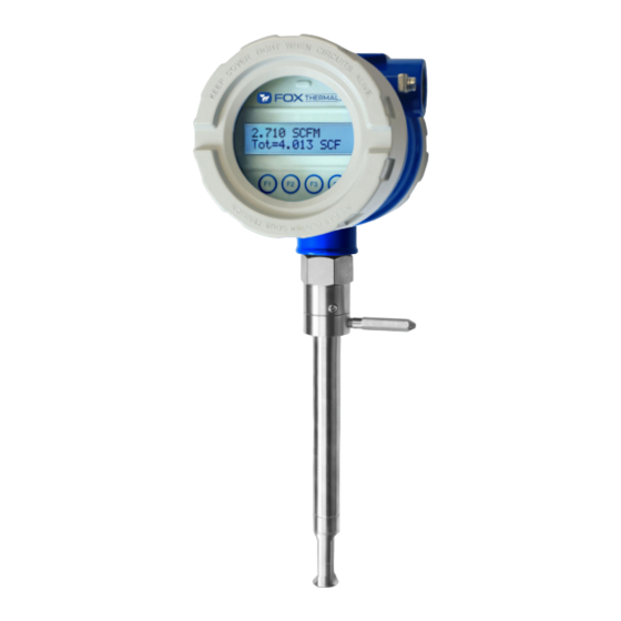
Page 3: Section A: Ft1 Troubleshooting
Section A: FT1 Troubleshooting Please refer to the troubleshooting section of the FT1 Manual. There is a link to the Fox model FT1 Instruction Manual located on the “Downloads” tab of the FT1 product webpage or here for quick reference: https://www.foxthermal.com/products/pdf/ft1/ft1-manual.pdf... -
Page 4: Section B: Ft1 Measurement Accuracy And Calibration
PLC/DCS. 7. If measuring a gas mixture, ensure the gas mixture equals 100%. If not, what gas are you currently measuring? Does the Gas-SelectX® setting in the FT1 closely match the composition of the gas being measured? 8. Check insertion depth, is the end of the sensor window 0.73" (18.5 mm) past the center line of the pipe? 9. - Page 5 Model FT2A Section A: FT2A Troubleshooting Please refer to the troubleshooting section of the FT2A Manual. There is a link to the Fox model FT2A Instruction Manual located on the “Downloads” tab of the FT2A product webpage or here for quick reference: https://www.foxthermal.com/products/pdf/ft2a/ft2a-manual.pdf 1.
- Page 6 Electronics Enclosure Extension Cable Remote Enclosure Sensor Wire Terminal numbers Wire Color Terminal Numbers Color Black Brown Yellow No Connection Shield Green White White Green White 6. Confirm the sensor resistances are correct. Turn off power to meter and disconnect sensor wires from TS8 (the sensor termination terminal strip •...
- Page 7 10. Check the direction of flow: Ensure the sensor elements are aligned correctly with the flow (±2 degrees). Note differences between • equal and unequal sensor types. Insertion type flow meters: Is the arrow on the flow meter probe pointing in the direction of flow? •...
- Page 8 Model FT3 Section A: FT3 Troubleshooting Please refer to the troubleshooting section of the FT3 Manual. There is a link to the Fox model FT3 Instruction Manual located on the “Downloads” tab of the FT3 product webpage or here for quick reference: https://www.foxthermal.com/products/pdf/ft3/ft3-manual.pdf 1.
- Page 9 6. Test/Check the LED status (Heartbeat) light of the FT3. Is the LED (green) blinking once per second? The LED lights can be viewed by unscrewing the front cap to reveal the display and configuration panel. • The LED status lights are visible behind the Display panel. To get a better view, remove the display panel by unscrewing the two screws on the display panel as shown below.
- Page 10 Carefully check for proper wire terminations at the sensor junction box and at the electronics housing. • Electronics Enclosure Extension Cable Remote Enclosure Sensor Wire Terminal numbers Wire Color Terminal Numbers Color Black Brown Yellow No Connection Shield Green White White Green White...
- Page 11 13. Check the direction of flow: Ensure the sensor elements are aligned correctly with the flow (±2 degrees). • Insertion type flow meters: Is the arrow on the flow meter probe pointing in the direction of flow? • Inline type flow meters: An inline meter will have the flow direction arrow on both the probe and flow •...
- Page 12 Model FT4A Section A: FT4A Troubleshooting Please refer to the troubleshooting section of the FT4A Manual. There is a link to the Fox model FT4A Instruction Manual located on the “Downloads” tab of the FT4A product webpage or here for quick reference: https://www.foxthermal.com/products/pdf/ft4a/ft4a-manual.pdf 1.
- Page 13 7. If measuring a gas mixture, have you checked to be sure that the mixture parts equal 100%? If not, what gas are you currently measuring? Does the Gas-SelectX® setting in the FT1 closely match the composition of the gas being measured? 8.
- Page 14 Model FT4X Section A: FT4X Troubleshooting Please refer to the troubleshooting section of the FT4X Manual. There is a link to the Fox model FT4X Instruction Manual located on the “Downloads” tab of the FT4X product webpage or here for quick reference: https://www.foxthermal.com/products/pdf/ft4x/ft4x-manual.pdf 1.
- Page 15 4. For DC powered FT4X models, test/check the fuse (can be viewed by removing the rear enclosure cap). With the power off, take a resistance measurement across the fuse to ensure it is a short circuit. • Acceptable resistance: <1 ohm. •...
- Page 16 8. If measuring a gas mixture, have you checked to be sure that the mixture parts equal 100%? If not, what gas are you currently measuring? Does the Gas-SelectX® setting in the FT1 closely match the composition of the gas being measured? 9.
Need help?
Do you have a question about the FT1 and is the answer not in the manual?
Questions and answers