Fox Thermal FT1 Manual
Thermal mass flow meter & temperature transmitter
Hide thumbs
Also See for FT1:
- Troubleshooting manual (16 pages) ,
- Troubleshooting manual (2 pages) ,
- Instruction manual (110 pages)

Related Manuals for Fox Thermal FT1


Summary of Contents for Fox Thermal FT1
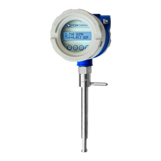
- Page 1 Fox Thermal THERMAL MASS FLOW METER & TEMPERATURE TRANSMITTER Model FT1 www.foxthermal.com | 399 Reservation Road Marina, CA. 93933 106012 Rev. H...
- Page 2 EMAIL: SERVICE@FOXTHERMAL.COM Download Technical Data Sheets from our website: www.foxthermal.com Fox Thermal believes that the information provided herein is accurate; however, be advised that the information contained herein is NOT a guarantee for satisfactory results. Specifically, this information is neither a warranty nor guarantee, expressed or implied, regarding performance, merchantability, fitness, or any other matter with respect to the products;...
-
Page 3: Table Of Contents
Model FT1 Table Of Contents 1. Introduction Page 4 a. Menu Trees Page 4 b. Quick Start Guide Page 12 2. Installation (Mechanical) Page 16 a. Installation Depth Page 20 b. Orientation of Flowmeter Page 21 c. Rotating the Probe/Enclosure Page 21 d. -
Page 4: Introduction
Model FT1 Introduction: Menu Trees Fig. 1.1: FT1 Menu Tree - Main Menu Enter menu by scolling to display 4 (p. 40) and entering the password (p. 47) MAIN MENU I/O FLO DSP EXIT Display Menu, p. 8 Flow Menu 1, p. 6 If RS485 hardware detected If HART hardware detected/with license If pulse/alarm hardware detected SET I/O SET I/O SET I/O COM 420 EXIT PUL 420 EXIT COM PUL 420 EXIT Communication... - Page 5 Model FT1 Introduction: Menu Trees Fig. 1.2: FT1 Menu Tree - Digital Output MAIN MENU I/O FLO DSP EXIT Set I/O PUL 420 EXIT (p. 46) Not used OUT= Pulse Pulse NXT OK HiFloAlm LoFloAlm HiTempAlm LoTempAlm Pulse Alarm output (p. 52) High Flow Alarm ...
- Page 6 Model FT1 Introduction: Menu Trees Fig. 1.3: FT1 Menu Tree - Flow Menu 1 MAIN MENU I/O FLO DSP EXIT FLOW MENU 1 DGN UNT FM2 EXIT Flow Menu 2 Menu, p. 7 (p. 56) DIAGNOSTIC FLO UNT=SCFM (p. 48) SIM ZRO EXIT NXT OK TMP UNT=° F Simulate Flow? NXT OK YES NO TmpRef=60 °F FloSim=0 SCFM CHG OK...
- Page 7 Model FT1 Introduction: Menu Trees Fig. 1.4: FT1 Menu Tree - Flow Menu 2 MAIN MENU I/O FLO DSP EXIT FLOW MENU 1 DGN UNT FM2 EXIT FLOW MENU 2 GAS SPC PRM EXIT Parameters (p. 51) (p. 54) Flow cutoff in selected units K fact = 0% Cutoff=12.5 SCFM CHG OK CHG OK ® Gas-SelectX Menu, p. 10 Pipe_id=4.026 In RESTORE DATABASE? Pipe id in inches or mm YES NO CHG OK...
- Page 8 Model FT1 Introduction: Menu Trees Fig. 1.5: FT1 Menu Tree - Display Menu MAIN MENU I/O FLO DSP EXIT DISPLAY/PASSWORD DSP PSW EXIT Display 1 Line 1 (p. 46) (p. 48) FLo rate DSP1L1=FLo rate PASSWD=1234 Total NXT OK CHG OK Elps Display 1 Temp Line 2 Alarm FLo rate DSP1L2=Total Total NXT OK Elps Display 2 ...
- Page 9 Model FT1 Introduction: Menu Trees ® Fig. 1.6: FT1 Menu Tree - Zero CAL-CHECK Menu MAIN MENU I/O FLO DSP EXIT FLOW MENU 1 DGN UNT FM2 EXIT DIAGNOSTIC MENU SIM ZR0 EXIT (p. 60) ZERO CHK MENU VER EXIT VERIFY ZERO? YES NO Process Zero and Stable? YES EXIT Verifying ZERO 0.512 T=123 Displays a number value Displays the test’s during test count down timer ZERO=2.321 ZERO=0.259 ZERO=0.911 Fail OK Pass OK Warning OK...
- Page 10 Model FT1 Introduction: Menu Trees Fig. 1.7: FT1 Menu Tree - Gas-SelectX Menu ® MAIN MENU I/O FLO DSP EXIT FLOW MENU 1 DGN UNT FM2 EXIT FLOW MENU 2 GAS SPC PRM EXIT (p. 62) Methane GAS=%Mix Select up to five gases for Gas Mix. Be sure NXT OK mixture equals 100%. Nitrogen Natural Gas Argon Propane Methane = 65 % Helium UP DN OK Oxygen Ethane Butane CO2 = 30 % Hydrogen UP DN OK Gas Mix...
- Page 11 Model FT1 Introduction: Menu Trees Fig. 1.8: FT1 Menu Tree - Engineering Display Enter: Press F1 & F2 at the same time Press F4 to return to normal mode 3124.6 SCFM Flow rate measured by the meter Display 10 CSV = 0.3432 Volt Current Sense Voltage of sensor measurement circuit Pulse=1234.5 cnt Digital control counts of Pulse output Display 11 mA_420=234 cnt Digital control count of 4 20mA output Elp=12.5 HR Elapsed time of meter operation Display 12 Stat(hex)=2800 Meter function and operation status code Alm=None Meter’s active alarms Display 13 FT1 V2.0 Firmware version of meter MB_Sn=P23949 Main board serial number Display 14 BB_Sn=P23945 Bridge board serial number...
-
Page 12: Quick Start Guide
12-28VDC 12-28VDC [refer to p. 33-p. 35 for more] Initializing... the front panel of the display or by using the FT1 View™ software tool. Record the settings in the spaces given for items A - E on the following page. - Page 13 After powering on your meter, check items A - E below by accessing the meter settings either through the front panel of the meter's display or by using the FT1 View™ software tool. been set in meter? (SCFM, KG/H, etc..)
- Page 14 Model FT1 Introduction Welcome Thank you for purchasing the Model FT1 Thermal Gas Mass Flow Meter from Fox Thermal. engineering effort has been invested to deliver advanced features, accurate measurement performance and outstanding reliability. This Instruction Manual contains the electrical and mechanical installation instructions as well as details for programming, maintaining and troubleshooting the meter.
- Page 15 RS485 Modbus RTU or BACnet MS/TP. There is also frequency is 100 Hz. FT1 View™ interfaces to the USB port and is a free PC-based software program that displays download on the Fox Thermal website. Industry standard communication options are available including optional RS485 Modbus RTU, BACnet MS/TP, or HART.
-
Page 16: Installation (Mechanical)
Model FT1 Installation Scope This section describes how to install the Fox Thermal Model FT1 Flow Meter and how to get For Insertion Types: 1. Determine lateral position on the pipe 2. Verify sensor installation depth 4. Determine if the display orientation must be changed For Inline Types 1. - Page 17 4. Mounting FT1 in direct sunlight can cause the temperature inside the enclosure to increase beyond design limits, resulting in failure of LCD display and reduced component life. It is recommended that a sunshade be installed to avoid direct 6.
- Page 18 Model FT1 Installation Instructions for Flow Meter Lateral Placement your meter type. Fig. 2.1: Upstream and Downstream Pipe IDs for Flow Meters INSERTION Branch Outlet Proper (installed by Irregular Flow Flow customer) Profile Profile FLOW 15X Pipe ID min. 10X Pipe ID min.
- Page 19 Model FT1 Installation Welding NPT Female Fitting to Pipe Directions: • 5. To verify that the correct hole position has been achieved,carefully slide the 0.75-inch WARNING! Do not force the 0.75-inch sensor through the 0.781-inch hole. Forcing it through the 0.781-inch hole can damage the probe! pipe's centerline.
-
Page 20: Installation Depth
Ø.75 PROBE Rotating the Enclosure The Model FT1 has been designed to allow the enclosure to rotate into four positions for Flow Direction Indicator. Then unscrew and remove the Flow Direction Indicator to allow the enclosure to swivel into the desired position. Then screw the Flow Direction Indicator back into... - Page 21 Model FT1 Installation Direction of Flow and Orientation of the Probe Sensor To rotate the enclosure/probe, unscrew the Flow Direction Indicator and the Set Screws, rotate the housing ±90° or 180°, and return the Flow Direction Indicator and Set Screws in order to secure the new placement.
-
Page 22: Changing The Orientation Of The Display
Model FT1 Installation Changing the Orientation of the FT1 Display The display can be rotated in 90° increments for optimal viewing of the screen. First, open the enclosure by unscrewing the enclosure cap and loosen the two captive phillips screws to open the display assembly. - Page 23 Model FT1 Installation Mounting Instructions - Compression Fittings The Model FT1 is mounted through a 7/8" hole and a 1" female NPT half coupling provided in 1½". • • When installing in a 2" pipe or larger, install the end of the probe 0.73" (18.5 mm) past p.
- Page 24 Model FT1 Installation Installation of a New Retractor Assembly NOTE! refer to Document #107590. 1. Remove collar clamp from probe using a 3/16" Hex Key. 2. Remove meter probe from retractor assembly and leave the ball valve open. 3. Install the valve assembly on the pipe, by tightening the Hex Nipple with a 1 3/8" wrench.
- Page 25 Model FT1 Installation obstructions. Carefully slide the probe through the retractor assembly and through the hole to see if there is interference by touching the pipe wall on the far side or until the probe cannot go deeper. Remove the retractor and rework the hole, if required.
- Page 26 Model FT1 Installation 6. Using the equation (L + D/2 + 0.73") from Figure 2.8, calculate the insertion depth and mark on the probe while measuring from the end of the probe. 7. Ensure there is enough clearance to remove the meter from the retractor. See the Retractor Clearance table in Fig 2.8 for the model code of your meter.
- Page 27 Model FT1 Installation 8. Insert probe back into valve assembly to the depth mark and hand-tighten the compression Flow Direction Indicator Swage Nut & Ferrules Swage Fitting Nut" on page 23). 11. Install collar clamp back on probe just below the collar spacer. Install collar so that the cable mounting hole is in line with the mounting hole on the bracket (see image in "Fig.
- Page 28 Do not open the enclosure when energized or an explosive atmosphere is present. • Connect earth ground to a chassis ground screw on the inside or outside of FT1 enclosure to reduce the potential of an electrostatic charging hazard. •...
-
Page 29: Signal Wiring
Wiring: General Wiring Instructions To wire the FT1, unscrew and remove the enclosure cap. If the meter has the display option, loosen the two captive screws on the display assembly and rotate it open to access the wiring terminals. Connect the power and signal wires to the terminal blocks according to the label and instructions on the following pages. - Page 30 6 Watts minimum. (With 12VDC power, the FT1 can use up to 500mA. With 24VDC power, the FT1 can use up to 250mA.) A 20 Watt or greater power supply is recommended to ensure it can provide enough current under all temperature, ventilation and power on conditions.
- Page 31 Model FT1 Wiring: Signal Wiring 4-20mA Output Wiring: Customer-Supplied Power Source Bring the 4-20mA wiring in through either conduit hub. Connect 4-20mA wiring as shown in the diagram below. Fig. 3.2: 4-20mA Output Wiring for Customer-Supplied Power Source Customer PLC or DCS...
- Page 32 4-20mA Output Wiring: Loop Power Provided by FT1 Bring the 4-20mA wiring in through either conduit hub. Connect the 4-20mA as shown in the diagram below. Fig. 3.3: 4-20mA Output Wiring for Loop Power Provided by FT1 Customer PLC or DCS +12 to 28VDC...
- Page 33 The pulse/alarm output is an open collector circuit capable of sinking a maximum of 20mA of current. Pulse or alarm selection is programmed using the display or FT1 View™. Only one option, pulse or alarm, can be active at a time.
- Page 34 The pulse/alarm output is an open collector circuit capable of sinking a maximum of 20mA of current. Pulse or alarm selection is programmed using the display or FT1 View™. Only one option, pulse or alarm, can be active at a time.
- Page 35 Termination Resistor Connect a termination resistor across the receive/transmit signals of the last device on the communication line. To connect the 121 ohm termination resistor on the FT1, set jumper W1 to the Terminated position, see Fig. 3.6. Disconnect the termination resistor on all other external RS485 devices. The termination resistor of the FT1 is disconnected by setting jumper W1 to the Open position.
-
Page 36: Hart Wiring
Model FT1 Wiring: HART HART Wiring The HART connections are made as shown in the diagram below. NOTE! changes the 4-20mA output to temperature, HART should report temperature. HART 4-20mA Output Wiring: Customer-Supplied Power Source The 4-20mA current loop and HART modem connections are made as shown in the diagram below. - Page 37 HART 4-20mA Output Wiring: Loop Power Provided by FT1 The 4-20mA current loop and HART modem connections are made as shown in the diagram below. Fig. 3.9: HART 4-20mA Output Wiring, Loop Power Provided by FT1 Customer PLC or DCS +12 to 28VDC...
-
Page 38: Start Up
The USB interface is a standard feature which allows communication with a PC to monitor FT1 Display and Configuration Panel The FT1 has a 2 line x 16 character display with 4 mechanical buttons. The meter can be the FT1. - Page 39 Pressing the F3 and F4 keys at the same time brings up the Reset Total screen (see p. 55) prompt. Fig. 4.2: FT1 Measurement Mode Display Screen Navigation F1 key: Moves up one screen F2 key: Moves down one screen 1456.5 SCFM...
-
Page 40: Programming
Model FT1 Operation: Programming Data Entry using the Display and Configuration Panel There are 2 basic types of menu entries: one for changing value or string and one for selecting from a selection list. To Change a Value or String : VALUE = 0.91234... - Page 41 Model FT1 Operation: Programming Main Menu If the password is accepted, the Main Menu screen will be shown: MAIN MENU EXIT This is the Main Menu screen for the programming mode. Press EXIT (F4) repeatedly until Analog 4-20mA Output The following menu allows the scaling of the analog 4-20mA output. From the Main Menu, press I/O (F1) to move to the 4-20mA output selection.
- Page 42 Model FT1 Operation: Programming Enter the value for the 20mA and press OK (F4) key to accept the setting. Then the following screen will display: 4 mA = 0 SCFM Enter the value for the 4mA and press OK (F4).
- Page 43 20mA and an alarm code will be generated. Pulse/alarm Output If the Pulse/alarm feature was purchased as the second output for the Model FT1, it can be accessed from the main menu, press I/O (F1) (screen appearance may vary).
- Page 44 (frequency), the output will stay at 100 Hz and the FT1 will issue an alarm code. Alarm Output If the Pulse/alarm feature was purchased as the second output for the Model FT1, press I/O (F1) key from the Main Menu screen.
- Page 45 Serial Communication Settings If RS485 Communication feature was purchased as the second output for the Model FT1, the Serial communication settings can be programmed by pressing I/O (F1) key from the Main Menu. The screen will show:...
- Page 46 Model FT1 Operation: Programming SET I/O EXIT Press COM (F1) to select Serial communication. The screen may show: Comm=Modbus Options for serial communication are: None MODBUS BACNET HART NOTE! selected communication type. If enabling a communication option, see the Communications Protocols section of this manual.
- Page 47 The second password is used to allow access to calibration factors and should normally never be changed unless advised by the Fox Thermal service department, or to set a new password in the event that the user forgets the Level 1 password.
- Page 48 Reference temperature and reference pressure settings can be accessed also. These values will be set at Fox Thermal using information supplied by the customer. These values can be changed to match a new application. The units setting is accessed from the Main Menu.
- Page 49 Model FT1 Operation: Programming FLOW MENU 1 EXIT Press UNT (F2) for Unit selection. The screen will show: FLO = SCFM Press NXT (F1) to change selection and OK (F4) to accept. NOTE! 55). WARNING! changing units. SCFM KG/S MMSCFD (MMCFD)
- Page 50 After the pressure unit selection is made, the display will show a menu to enter the reference pressure: PresRef= 14.7 Press CHG (F1) to change it and OK (F4) to accept. After the reference pressure is accepted, the FT1 will recalculate and display gas density at user's reference temperature and pressure:...
- Page 51 Model FT1 Operation: Programming DNS = 1.2930 KG/m3 The gas density is for information only. Press OK (F4) to continue. Flow Parameters MAIN MENU EXIT The menu is accessed from the Main Menu by pressing FLO (F2): FLOW MENU 1...
- Page 52 Model FT1 Operation: Programming Pipe Inside Diameter (ID) To set the Pipe Inside Diameter: Pipe_id = 3.068 In Enter the pipe ID in inches or millimeters and then press OK (F4). pipe/duct is a square or rectangle, the hydraulic diameter (equivalent value for a round pipe) must be entered for the pipe ID.
- Page 53 Model FT1 Operation: Programming should be set to zero. Press OK (F4) to accept the value. High Temperature Alarm To set the parameters for a High Temperature Alarm: HiTmpAlm = 200° F This is the upper temperature limit alarm value that can be associated with the alarm output.
- Page 54 Model FT1 Operation: Programming FLOW MENU 2 EXIT The following screen will be displayed: Press CHG (F1). Add the correction factor and press OK (F4). For Example: If an existing K Factor is present, add the additional K Factor to the existing value.
- Page 55 The non-resettable totalizer is only recommended for applications that require it. After it has been enabled, your FT1’s totalizer and elapsed time counters will be non-resettable. SET NRT? Press YES (F1) ONLY if you want to set the NRT.
- Page 56 Model FT1 Operation: Programming Simulation and demonstration purposes. Make sure to return all of these simulation values to zero, before returning to the normal mode of operation. CAUTION! If the 4-20mA and/or the pulse/alarm outputs are connected to controllers, false controller action.
- Page 57 Model FT1 Operation: Programming Simulate Temp? Press YES (F1) to continue. TmpSim = 0 C Enter the value and then press OK (F4). NOTE! Enter zero to disable this feature. ENABLE SIM? Press YES (F1) to start the simulation mode, otherwise press NO (F4). Upon pressing either key, the program will return to the FLOW MENU 1 screen.
- Page 58 Model FT1 Operation: Zero CAL-CHECK ® Calibration of the Fox Thermal Model FT1 Thermal Flow Meter Calibration Validation Calibration Validation allows our customers to validate the accuracy and functionality of the that the meter is running accurately. ® Zero CAL-CHECK ensures the repeatability, functionality of the sensor and its associated signal processing circuitry, and cleanliness of the sensor.
-
Page 59: Zero Cal-Check
Model FT1 Operation: Zero CAL-CHECK ® ® Fig. 4.3: Normal Mode vs. Zero CAL-CHECK Mode NORMAL MEASUREMENT MODE Zero CAL-CHECK™ MODE Calibration Validation Outputs PASS/FAIL MICROPROCESSOR MICROPROCESSOR BASELINE RATE MASS FLOW COMPARISON CALCULATION SIGNAL SIGNAL PROPORTIONAL ZERO FLOW RATE FLOW RATE DDC-Sensor™... - Page 60 Model FT1 Operation: Zero CAL-CHECK ® ® Performing the Zero CAL-CHECK Calibration Validation Test ® The Zero CAL-CHECK less than 5 minutes to complete. At the conclusion of the test, a Pass or Fail message will be displayed. Press F4 at the conclusion of the test to return to normal measuring mode or to terminate the test.
- Page 61 • Fail: greater than ±1.0 If a "Warning" or "Fail" result is displayed, Fox Thermal recommends that the probe be removed from the pipe, the sensor cleaned, and the test be performed again. If the test was If a "Warning" or "Fail" result is displayed after performing the test a second time, please call...
- Page 62 Gas Selection Menu Feature ® This menu allows the user to select a gas or gas mix from a pre-calibrated list of gases/gas mixtures available on the Fox Thermal Model FT1 Flowmeter. Gases and gas mixes available in the Gas-SelectX feature include: ®...
- Page 63 Model FT1 Operation: Gas-SelectX ® SET PARAMETERS? Press YES (F4) and the following screen will prompt the user to enter the password if it is active: PASWD:_ Enter the correct password and press OK (F4) to enter it. NOTE! Default password is 1234.
- Page 64 Model FT1 Operation: Gas-SelectX ® The display may show: GAS=Methane EXIT From this screen, the user will be able to access two aspects of the Gas-SelectX menu: ® 1. Pure Gas = Choosing from a list of available gases, or...
- Page 65 Model FT1 Operation: Gas-SelectX ® The screen will show: This screen shows the percentage of the gas mixture allocated to methane. In this case, it CHG (F1). To set the percentage of methane in the gas mix, press UP (F1) or DN (F2).
- Page 66 Model FT1 Operation: Gas-SelectX ® One of the following messages will appear: Shows only if no error is detected. Shows only if no error is detected. Pressing OK allows exit to menu. Pressing OK allows exit to menu. Shows only if gas mix does not equal...
- Page 67 NOTE! The data shown in brackets < > represents one byte of data. Modbus Indicators LED indicator LP3 cycles on and off to indicate that the FT1 is operating. LED indicator LP2 blinks when Modbus signals are received and LP1 blinks when Modbus...
- Page 68 2) Command 04: Read input register. 3) Command 06: Preset single register Read Holding Registers (command 03) This command reads the basic variable from the FT1 and has the following format: Request: <Meter Address> <Command code=03> <Register start address high> <Register start address low>...
-
Page 69: Gas-Selectx
Model FT1 FT1 Commands Supported by Modbus Register Modbus Data Type Scaling Comment Address Address 0x0C 40013 Total in selected units *100 Total in selected units * 100 0x0D 40014 Spare/ Not used 0x0E 40015 Spare/ Not used 0x0F 40016... - Page 70 40077 Hydrogen percent Read Input Register (FT1 Status, Command 04) This command is used to report the FT1 status information. Request: <Meter Address> <Command code=04> <Register address =0> <Register address =0> <Register count =0> <Register count =1> <CRC high> <CRC low>...
- Page 71 Model FT1 FT1 Commands Supported by Modbus Comment Pulse hardware detected Busy Busy Not used Not used Not used Not used Zero CAL-CHECK in process Zero CAL-CHECK fail Zero CAL-CHECK aborted Zero CAL-CHECK warning Preset Single Register (Command 06) This command is used to perform miscellaneous functions such as clearing the totalizer and elapsed time.
- Page 72 Model FT1 Modbus Programming Enter the Programming Mode - Modbus RTU (RS485) Press the F1 or the F2 key repeatedly, in the normal running mode, until the following screen is shown. This enters the programming mode: SET PARAMETERS? Press YES (F4) and then the following screen will prompt the user to enter the password if...
- Page 73 Model FT1 Modbus Programming Communication Protocol and Parameters To program the communication parameters, start at the Main Menu: MAIN MENU EXIT Then press I/O (F1) to set Inputs/Outputs: SET I/O EXIT Then press COM (F1) to select communication parameters. Set Bus protocol for Modbus:...
- Page 74 Model FT1 Modbus Programming Parity=EVEN Press NXT (F1) repeatedly until the correct selection is shown and then press OK (F4) to accept the setting. Selections are: Address=02 Press CHG (F1) to change the address and then press OK (F4) to accept the setting.
-
Page 75: Bacnet Ms/Tp
Analog Input 4 = Elapsed Time since reset BACnet Indicators LED indicator LP3 cycles on and off to indicate that the FT1 is operating. LED indicator LP2 blinks when BACnet signals are received and LP1 blinks when BACnet signals are transmitted. - Page 76 9600, 19200, 38400, 57600, 76800, 115200 FT1 Character sets supported: ANSI X3.4, UTF-8 Fox Thermal BACnet vendor ID: 650 For more information about BACnet visit http://www.bacnet.org/. Enter the Programming Mode - BACnet MS/TP (RS485) Press the F1 or the F2 key repeatedly, in the normal running mode, until the following screen is shown.
- Page 77 Model FT1 BACnet Programming Communication Protocol and Parameters To program the communication parameters, press I/O (F1) key from the main menu. MAIN MENU EXIT This is the main menu for the programming mode. To exit the programming mode, press EXIT (F4) communication output.
- Page 78 Model FT1 BACnet Programming Next select the MS/TP Mac address. The selection is from 0-127. Please note that only one device can be on a MS/TP Mac address. MAC_ADD=23 Next select the MS/TP Max Master using CHG (F1). The selection is from 0-127. Press OK (F4) to accept the setting.
-
Page 79: Hart
Model FT1 HART Introduction Scope The Fox Thermal Model FT1 transmitter complies with HART Protocol Revision 7.1. This section (e.g., the Engineering Unit Codes supported). The functionality of this Field Device is described capable Host Applications. Purpose This section provides a complete description of this Field Device from a HART Communication perspective. - Page 80 4-20mA output is set to report temperature, HART communication will report the 4-20mA HART Indicators LED indicator LP3 cycles on and off to indicate that the FT1 is operating. LED indicator LP2 blinks when HART signals are received and LP1 blinks when HART signals are transmitted (if nothing is connected to the 4-20mA output, LP2 will be on continuously).
- Page 81 Model FT1 HART Programming Extended Device Status This bit is set if a sensor error is detected. "Device Variable Alert" is set if the PV is out of limit. Additional Device Status (Command #48) information. These bits are set when an alarm or error condition is present. The bit automatically clears when the condition returns to its normal state.
- Page 82 Fixed current mode is implemented, using Command 40. This mode is cleared by power loss or reset. Damping Damping is standard, affecting only the PV and the loop current signal. Capability Checklist Manufacturer, model Fox Thermal Instruments, FT1 Device type Transmitter HART revision Device Description available Number and type of sensors...
- Page 83 Model FT1 HART Programming Enter the Programming Mode - HART Press the F1 or the F2 key repeatedly, in the normal running mode, until the following screen is shown. This enters the programming mode: SET PARAMETERS? Press YES (F4) and then the following screen will prompt the user to enter the password if...
-
Page 84: Maintenance
CAUTION! BE SURE POWER TO METER IS SWITCHED OFF BEFORE ATTEMPTING TO ACCESS ELECTRONICS. If there is a problem and a loose connection is not found, please contact Fox Thermal Customer Service for technical assistance at (831) 384-4300. -
Page 85: General
103. Flow Calibration and Calibration Validation To ensure continued high accuracy of your Model FT1 Flow Meter, Fox Thermal provides a full NIST traceable calibration. It is recommended that the meter's accuracy be checked annually by performing the Zero CAL-CHECK Calibration Validation test. - Page 86 Model FT1 Maintenance: Retractor Option Instructions for Removing and Inserting the Meter from a Pressurized Pipe using the Retractor WARNING! Possible injury or damage to equipment may occur if the retractor is not used correctly. Please read the following instructions carefully prior to using the retractor.
- Page 87 Model FT1 Maintenance: Retractor Option Step 2 - Remove the Probe from the Retractor Body 6. Retighten the Swage Fitting. 7. Remove the Collar Clamp by using a 3/16" Hex Key. 8. Carefully slide the probe out of the retractor while supporting the meter.
- Page 88 Model FT1 Maintenance: Retractor Option How to Insert the Probe into the Flow Stream (Valve closed, System Pressurized) 1. Carefully, slide the probe into the retractor. 2. Install the collar clamp just below the collar spacer, and tighten it in place on the probe.
- Page 89 Model FT1 Maintenance: Retractor Option 4. Verify that the probe is aligned with the centerline of the pipe, and pointed in the direction Figure 8.4 Flow Direction Indicator Swage Nut & Ferrules Swage Fitting 5. Secure the probe in place by tightening the Swage Nut with a 1 1/8" wrench and a 1 1/4"...
-
Page 90: Troubleshooting
Customer Service Department, Technical Assistance at (831) 384-4300. LED Indicators The LED indicators near the terminal blocks of the FT1 display the status of the FT1. The Heartbeat LED blinks fast when the FT1 is powered up, and blinks about once a second when the FT1 operates normally. - Page 91 Model FT1 Model FT1 Troubleshooting: General Problem Possible Cause Action Meter resets 1. Electromagnetic 1. Check meter power cycles value interference (EMI) 2. Press and release F1 and F2 at the 2. Low power supply voltage or intermittent Engineering screens.
- Page 92 Make sure the meter is not being affected by vibration or other movement • Allow the meter to stabilize without being moved or touched for 15 minutes • Try the test again • If the meter fails again, contact Fox Thermal Technical Assistance at 831-384-4300...
- Page 93 "Wiring Precautions" in Wiring section (p. 28) for further guidance. 2. Inadequate power source. The FT1 requires 12 to 28VDC at up to 6 Watts to operate. A 20 Watt power supply is recommended for powering the FT1 to ensure it operates properly under all conditions. If the voltage supplied at the input terminals of the FT1 is not within the range of 10VDC to faulty 4-20mA, pulse and communication interface.
- Page 94 Refer to the MAIN MENU on p. 4 of this Manual. Use the Set range I/O section to verify range limits. Busy Meter is recalculating new parameters. Database CRC Error Refer to the Reset CRC section on p. 54 of this manual. Verify the error. Contact Fox Thermal Service Department for possible causes.
- Page 95 0-2,500 0-3,600 0-3,950 NOTE! To determine if the FT1 will operate accurately in NOTE! Standard conditions of air at 70°F and one other pipe sizes, divide the maximum flow rate by the pipe atmosphere. Consult factory for other gases and for flow ranges above those listed.
- Page 96 Enclosure: -40 to 158°F (-40 to 70°C)* *NOTE! Input Power: 12 to 28VDC, 6 watts minimum (CE requirement) Full Input Power Range: 10 to 30VDC. A 20 Watt or greater power supply is recommended to power the FT1. Outputs: Channel 1: indication per NAMUR NE43.
-
Page 97: Agency Approvals
Model FT1 Physical Specs Probe diameter: ¾" Sensor material: 316 stainless steel Enclosure: NEMA 4, aluminum, dual ¾ Flow Meter Installation: plied ¾ Agency Approvals CE Mark: Approved Electrical Equipment for Measurement, Control, and Lab Use: EN61326-1:2013 Pressure Equipment Directive: 2014/68/EU Weld Testing: EN ISO 15614-1 and EN ISO 9606-1, ASME B31.3... -
Page 98: Dimensions
Model FT1 Appendices: Dimensions Fig. 7.1 Insertion Meter Dimensions Measurements shown in inches (millimeters). 5.97 [151.6] 4.64 [118.0] 2.60 [66.1] 2X 3/4˝ FNPT PORTS 6.70 [170.3] ELECTRONICS ENCLOSURE SET SCREWS FLOW DIRECTION INDICATOR PROBE ˝LL˝ NOMINAL LENGTH C L SENSING AREA .73 [18.5]... - Page 99 Model FT1 Appendices: Dimensions Fig. 7.2 Insertion Meter with 150 psig Retractor Dimensions Measurements shown in inches (millimeters). (155.0) 4.64 (118.0) (61.0) 6.70 2X 3/4" NPT (160.0) (170.3) FEMALE RESTRAINT CABLE RESTRAINT CABLE MOUNT RETRACTOR WITH 1 INCH FULL PORT BALL VALVE 9.0±.3...
- Page 100 Model FT1 Appendices: Dimensions Fig. 7.3 Inline Meter with Flow Body and NPT End Connections - Dimensions Measurements shown in inches (millimeters). 5.97 [151.6] 4.64 [118.0] (61.0) 2X 3/4˝ FNPT PORTS 6.70 (170.3) FLOW DIRECTION ELECTRONICS INDICATOR ENCLOSURE “H” 2x NPT Male Thread “L”...
- Page 101 Model FT1 Appendices: Dimensions Fig. 7.4 Inline Meter with Flow Body and 150lb RF Flange End Connections - Dimensions Measurements shown in inches (millimeters). 5.97 [151.6] 4.64 [118.0] (61.0) 2X 3/4˝ FNPT PORTS 6.70 (170.3) FLOW DIRECTION ELECTRONICS INDICATOR ENCLOSURE “H”...
-
Page 102: Warranty
Appendices: Warranty Warranty (a) Fox Thermal (hereafter FOX) warrants that the products furnished under this Agreement will be free from defects in material and workmanship for a period of one year from the date of shipment. The customer shall provide notice of any defect to FOX, within one week after the Customer’s discovery of such defect. -
Page 103: Returning Your Meter
7-10 days (not including shipping or peak production times). If you have already shipped your meter to Fox Thermal for servicing and would like to check foxthermal.com and you will hear from a Customer Service Rep within 1 business day of your requested update. - Page 104 Model FT1 Glossary of Terms and Definitions NLPH Normal Liter per Hour American Wire Gauge NLPM Normal Liter per Minute Bara Bar absolute Normal cubic Meter Contact NM3/H Normal cubic Meter per Hour Calibration NM3/M Normal cubic Meter per Change...
-
Page 105: Index
Model FT1 Index Index Programming Analog 4-20mA Output, p. 41 Alarm Output, p. 44 Access to Electronics, p. 28 Changing values or strings, p. 40 Alarm Codes, p. 94 Display Setup, p. 46 Alarm wiring, p. 33 Filter value, p. 52 Analog 4-20mA output, p. - Page 106 Wiring Definition of Terms Troubleshooting Tips Notes and Information WARNING! is used to indicate a hazardous situation which, if not avoided, could result in death or serious injury. CAUTION! - is used to indicate a hazardous situation which, if not avoided, could result in minor or moderate injury.
Need help?
Do you have a question about the FT1 and is the answer not in the manual?
Questions and answers