Table of Contents
Advertisement
Quick Links
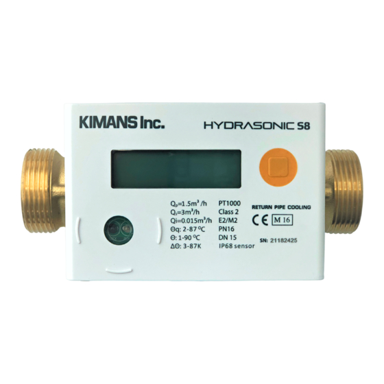
HYDRASONIC S8
ULTRASONIC HEATING/COOLING METER
Attention:
• Installation should only be carried out by qualified, trained personnel
• Violation and removal of the manufacturer's seals is not allowed, otherwise the warranties are void
• Welding on pipes near the meter is prohibited. The device must be dismounted before welding
• Eliminate the possibility of flooding the electronic unit
• The ambient temperature should be between 0 °C and 55 °
User Manual
Advertisement
Table of Contents

Summary of Contents for Kimans HYDRASONIC S8
- Page 1 HYDRASONIC S8 ULTRASONIC HEATING/COOLING METER Attention: • Installation should only be carried out by qualified, trained personnel • Violation and removal of the manufacturer's seals is not allowed, otherwise the warranties are void • Welding on pipes near the meter is prohibited. The device must be dismounted before welding •...
-
Page 2: Table Of Contents
Table of content General ..................................3 1.1 Operating conditions .............................. 3 2. Transport and storage ..............................4 3. Assembly / Installation ..............................4 3.1 Preparatory work ..............................5 3.2 Installation of flow sensor ............................. 5 3.2.1 Flow metering section location in a pipeline ..................... 5 3.2.2 Requirements of straight-line sections ...................... -
Page 3: General
1. General This guide is intended for trained specialized personnel. For this reason, no basic working steps are included. The meter tamper-evident seal must not be damaged! A damaged seal will result in immediate invalidation of the factory warranty and verification or declaration of conformity. -
Page 4: Transport And Storage
2. Transport and storage Unpacking Energy meter are measuring devices and must be handled with care. To protect against damage and soiling, they should only be unpacked immediately prior to installation. Transport The transport of the meter is permitted only in the original package. When sending wireless measuring instruments / components by air, deactivate the wireless before shipping. -
Page 5: Preparatory Work
When choosing the installation location, make sure that the meter is perfectly accessible for service and operating personnel. It is recommended that shut-off valves are fitted before and after the meter to simplify removing the meter. 3.1 Preparatory work ▪ Rinse the conduit thoroughly. ▪... - Page 6 Example of installation of Temperature sensor pocket of the return pipeline by means of a tee...
-
Page 7: Requirements Of Straight-Line Sections
3.2.2 Requirements of straight-line sections Flow metering section DN15…50 does not require to have straight sections before and after of flow sensor. Installation after the valve at a distance shorter than 5D without straight sections prohibited (fully Installation at the highest point of the system is opened full-bore ball valve excluded). -
Page 8: Mounting Rtd
3.3.1 Mounting RTD 1 – temperature sensor; 2 – Temperature sensor holder; 3 – Sealing ring For DN15…40 T1 pre-installed into flow sensor pipe (see figure): T2 should be installed in specialized fittings for DN15…25 with a thread for connecting RTD. Installation into such fittings does not require additional sealing. - Page 9 RTD can also be installed in a tee. To do this, use a special adapter (pos.3), which is directly screwed into the RTD holder (pos.2).
- Page 10 For DN greater than 50 installations of both RTD is carried out by means of a protective sleeve (pos.3), fig. below If temperature sensor t1 has to be installed separately (not inside flow metering section), orifice in the flow metering section must be plugged with a blind plug from the delivery set of the meter. 1 –...
-
Page 11: Communication
4. Communication 4.1 M-Bus wired A 2 pin M-Bus line lead out of the housing. Connect the M-Bus line with the marked connections of the M-Bus Master. Here it concerns a serial interface for communication with external devices (M-Bus control centers), ▪... -
Page 12: Display Menu
5. Display Menu 5.1 Overall Menu Structure... -
Page 13: Main Display
5.2 Main Display Short press < 3 sec Long press > 3 sec... -
Page 14: Test Display
5.3 Test Display... -
Page 15: Information Display
5.4 Information Display... -
Page 16: Error Display
5.5 Error Display... -
Page 17: Maintenance
6. Maintenance Flow sensor and temperature sensor may not be disconnected from the integrator. After repair work, perform recalibration in an accredited testing agency. Information concerning reconditioning or maintenance can be found in the processing concept (this will be made available for laboratories and testing agencies upon request). 7. - Page 18 Kimans Inc. www.kimans.com...


Need help?
Do you have a question about the HYDRASONIC S8 and is the answer not in the manual?
Questions and answers