
Related Manuals for SOMMER RG-30


Summary of Contents for SOMMER RG-30
- Page 1 RG-30, RG-30a Flow velocity Measurement System Manual Setup version 2.38 (Firmware 2.96) 25 November, 2019 Sommer Messtechnik All rights reserved.
- Page 2 6842 Koblach Austria This manual or parts of it may only be copied or passed on to third parties with written permission of Sommer Messtechnik. This applies to printed as well as digital issues of this manual. Sommer Messtechnik Strassenhäuser 27...
- Page 3 FCC ID: UXSIMS944 Feedback Should you come across any error in this manual, or if you miss information to handle and operate the RG-30 we are very grateful for your feedback to office@sommer.at.
- Page 4 Prior to installation of equipment inform the owner of the measurement site or the authority responsible for it. Upon completion, secure the installation from trespassers. Maintenance and repair must be performed by trained personnel or an engineer of Sommer Messtechnik. Only replacement parts supplied by Sommer Messtechnik should be used for repairs.
-
Page 5: Table Of Contents
Content What is the RG-30? Unpacking How do I start? Connect the RG-30 to a PC Configure the sensor Acquire measurements Specifications Connectors Main Connection cable for connector MAIN How does the RG-30 work? Flow velocity 6.1.1 Principle of measurement 6.1.2... - Page 6 What can I do with it? How do I install it? 9.2.1 System requirements 9.2.2 Installation procedure 10 How do I configure the RG-30? 10.1 Configuration with Commander support software 10.2 Configuration with a terminal program 10.3 Configuration errors 10.3.1 Device messages 10.3.2...
- Page 7 11.5.3 How do I wire it? 11.5.4 How do I configure it? 11.5.5 How do I switch back to Sommer protocol? 11.5.6 Which commands are available? 12 Analog output 12.1 What can I do with it? 12.2 How do I wire it? 12.3 How do I configure it?
- Page 8 D-F-A Minimum velocity D-F-B Maximum velocity D-F-C Meas. spot optimization D-F-D Measurement type D-F-E Stop, min. quality (SNR) D-F-F Stop, max. opp. direction D-F-G Stop, number of valid meas. D-F-H Stop, behavior D-F-I Stop, replace value D-F-J Meas. spot weighting 13.4.7 4-20 mA output IOUT3 D-G-A...
- Page 9 View setup Device status Set factory default Temp. load factory default Relaunch program Replace program Appendix A Unwanted reflections Open channel Closed channel...
-
Page 10: What Is The
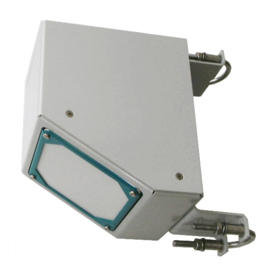
1 What is the RG-30? The RG-30 radar sensor is a measurement device for the contact-free determination of the flow velo- city of open rivers and channels. The sensor detects the surface flow velocity by the principle of the Doppler frequency shift. -
Page 11: Unpacking
2 Unpacking When unpacking your RG-30 sensor box please make sure that the following items are present: Item RG-30 sensor in the required version Manual on USB stick In case of missing or damaged items please contact your Sommer sales partner. -
Page 12: How Do I Start
7. Click Connect to establish a connection with the RG-30. If the connection was successful a green icon is displayed at the top-right corner of the Commander window. 8. Select the tab... -
Page 13: Configure The Sensor
Set the parameters of the velocity measurement (see Velocity measurement) 4. Optional: Configure analog outputs (see How do I configure it?) 5. Send any modifications to the RG-30 by clicking Upload modified parameters to device. Acquire measurements Select the tab Measurement (F3) and click Start polling measurements. -
Page 14: Specifications
4 Specifications Physical and environmental Power supply 6...30 VDC; Reverse voltage protection, overvoltage protection Power consumption at Standby approx. 1 mA Active measurement approx. 110 mA 12 VDC Outputs RS-485 ASCII / Modbus RTU SDI-12 Analog output 4…20 mA (14 bit, max. load 250 Ω) Operating temperature -35…60 °C (-31…140 °F) Storage temperature... - Page 15 Radar opening angle 12° Distance to water surface 0.50…35 m Vertical inclination Measured internally Automatic vertical angle compensation Accuracy ± 1 ° Resolution ± 0.1 ° Figure 3 RG-30 dimensions Manual...
-
Page 16: Connectors
1 x RS-485 (1200…115200 Baud) RS485 B SDI-12 interface SDI-12 1 x SDI-12 (1200 Baud) Switched digital output DIG-OUT Max. 1.5 A IOUTGND Analog ground Analog outputs ( RG-30 a only) IOUT3 Velocity (4…20 mA) Table 1: Configuration of connector MAIN Manual... -
Page 17: Connection Cable For Connector Main
NOTE The analog outputs and the trigger input are referenced to GND on pin Connection cable for connector MAIN The 12-pin connection cable is routed through one of the rubber-sealed holes on the front or back of the metal housing. Color Function Description... -
Page 18: How Does The Rg-30 Work
6 How does the RG-30 work? Flow velocity 6.1.1 Principle of measurement The contact-free measurement of the flow velocity is based on the principle of the Doppler Effect. The integrated velocity radar sensor transmits a signal with a constant frequency in a specific angle... -
Page 19: Flow Direction Separation
6.1.4 Inclination angle measurement As the RG-30 sensor is directed in a specific angle towards the water surface an angle correction has to be applied. The RG-30 measures its vertical inclination with an internal sensor and applies an automatic angle correction. - Page 20 is about 2 mm depending on the used frequency. For very slow moving rivers this requirement might not be fulfilled and a continuous and correct velocity measurement cannot be guaranteed. Manual...
-
Page 21: Installation
Hydraulic requirements Stationary waves There must be no stationary waves present in the field of view of the RG-30 as they can negatively influence the measurement accuracy. Stationary waves may be caused by big stones and other obstacles; their impact depending on water level. Stationary waves cause errors in angle as the radar impulse is partly reflected from them and not the plane water surface. - Page 22 Installation above open channels or rivers The RG-30 can be mounted in a range between 0.5 to 15 m above the water surface. With the exten- ded measurement range the RG-30 can be installed at a height up to 35 m above the water surface.
-
Page 23: Documentation
Installation underneath bridges When the RG-30 is installed underneath a bridge it has to be assured that no rain or melt water is dripping through the field of view of the velocity radar. The occurrence of such events may influ- ence the measurement considerably. -
Page 24: Power Supply
7.3.2 Power supply The RG-30 is designed for extreme environmental conditions at remote sites and with no grid con- nection. The sensor switches automatically into standby-mode between measurements and thus consumes only approx. 3.5 Ah per day (measurement duration 30 sec and measurement interval 60 sec) which can be supplied by a 12V-solar-generator mounted to the mast. -
Page 25: Lightning Protection
It is recommended to equip the RG-30 sensor with properly dimensioned lightning protection. Con- sult an expert for advice. The RG-30 is protected against overvoltage. If a data logger is mounted with the RG-30, its ground lug must be properly connected to earth ground. -
Page 26: Maintenance
During operation the RG-30 continuously performs a self-check to identify any abnormal system behavior or device failure. This self-check is returned by the RG-30 as a code (SFCH-code) with a value of 1 to 16. In the table below the SFCH-code together with their cause and solution. An icon as specified in the legend below is linked to each SFCH-code to indicate the significance of a detec- ted abnormality. - Page 27 SFCH- Symbol Description Cause Solution Code Sensor returns Sensor may not have Check correct sensor 999997, i.e., level been connected cor- installation (facing can not be measured rectly or is mal- water surface) and or measurement functioning. wire connections. If error persists, value has not been replace level sensor.
- Page 28 SFCH- Symbol Description Cause Solution Code Only applicable to Level sensor may be Check/adapt settings RQ-30L. Water level is configured incor- of water level sensor. above W_Q, Q-30 fix- rectly, e.g., sign of ation level. water level range may be inverted. Not specified Velocity indicates Sensor may not be...
- Page 29 SFCH- Symbol Description Cause Solution Code Quality (SNR) is insuf- Sensor may not be Check/adapt settings ficient in both flow dir- properly configured in menus Velocity (v) ections or is malfunctioning. Tech. velocity (v). If error persists, adjust sensor position, increase Stop, max.
- Page 30 SFCH- Symbol Description Cause Solution Code Water level is above May occur if W-v Check/adapt settings WMA, maximum learning has been in menu Level (W) level. optimized for low perform a level adjust- water levels (high ment with water levels are extra- Adjustment.
- Page 31 SFCH- Symbol Description Cause Solution Code Values of WCF, cease Occurs if W-v learning Check/adapt settings to flow level, WLL, low is not used. in menu Level (W) level border perform a level adjust- WMA, maximum level ment with are equal. Adjustment.
- Page 32 Symbol Status Normal operation with optimized setup Normal operation Table 5: Device status symbols Manual...
-
Page 33: Support Software Commander
9 Support software Commander What can I do with it? The Commander is a multipurpose software tool to configure and operate any Sommer Mess- technik device. It offers the following functions: Communication with Sommer Messtechnik sensors and data loggers via serial connection, modem, socket, IP-call and Bluetooth®... - Page 34 Read the instructions and click Next Select the installation type and click Next Manual...
- Page 35 Only for me No admin rights are required. Updates are only available to the user who installed the software. Installation folders: User program folder: Users\User\AppData\Local\Programs\Sommer\Commander Data structure: Users\User\AppData\Local\Programs\Sommer Specific folder (default): C:\Sommer\Commander Data structure (default):...
- Page 36 Standard program folder: Program Files (x86)\Sommer\Commander Data structure: Users\Public\Public documents\Sommer Specific folder (default): C:\Sommer\Commander Data structure (default): C:\Sommer Select the installation directory and click Next. Select the features to be installed and click Next. Manual...
- Page 37 Click Install to start the installation. Click Finish to complete the installation. Manual...
- Page 38 Manual...
-
Page 39: How Do I Configure The
Configuration with a terminal program 10.1 Configuration with Commander support software Follow the steps below to modify the configuration parameters of the RG-30: 1. Establish a connection between your PC and the RG-30 as described in Connect the RG-30 to Select the tab... - Page 40 Save the parameter file to your PC by clicking Save parameter file. This step is recommended to track any configuration changes. Manual...
-
Page 41: Configuration With A Terminal Program
The Commander software ships with an integrated terminal program. However, communication with the RG-30 can be performed with any terminal program. Follow the steps below to modify the configuration parameters of the RG-30: 1. Establish a connection between your PC and the RG-30. - Page 42 NOTE As an unwanted switching into the menu mode has to be avoided the timing of the three question marks ??? is very restrictive and must never be finished with Return/Enter. This is especially import- ant for command line tools, which may automatically send a closing "Carriage return”.
-
Page 43: Configuration Errors
10.3 Configuration errors 10.3.1 Device messages During configuration via RS-485 the RG-30 may return the following messages. The device messages are bit-coded and returned in hex format. If multiple messages are present the message codes are summed up. Message code... -
Page 44: Conflict Messages
PLEASE NOTE: Please perform a "W-v table reset"! Table 6: Device messages 10.3.2 Conflict messages During configuration via RS-485, the RG-30 may return conflict messages after one or more para- meters have been changed and uploaded to the device. An example is shown in Figure Figure 9... -
Page 45: What Do I Need To Configure
Maximum velocity below 0.01 m/s. Table 7: Conflict messages 10.4 What do I need to configure? When first setting-up a RG-30 at a measurement site, the parameters described below may need to be adapted. 10.4.1 General settings Language/Sprache The menu language. -
Page 46: Velocity Measurement
These conditions are defined by the settings under Velocity (v) Tech. velocity (v) Viewing direction The viewing direction of the RG-30 sensor in relation to the flow direction of the river, either upstream or downstream. Possible flow directions The setting to define if the river only flows in one direction or if two flow directions can occur, e.g. - Page 47 If the RG-30 sensor is mounted stably it is sufficient to measure the installation angle with the first measurement after a sensor restart. If the sensor can move it is recommended to perform an inclination measurement with each velocity measurement.
-
Page 48: Serial Communication
Modbus SDI-12 11.2 Which data do I get? The measurement values returned by the RG-30 are arranged in a fixed sequence and identified by an index. They are divided into three groups and can be selected in information. 11.2.1 Main values... -
Page 49: Analysis Values
RMS at the PIC Diagnostic variable Amplification Value of the amplification regulation Amplification relation Diagnostic variable Signal relation Diagnostic variable Error code for diagnostic use of Sommer Messtechnik only not used not used not used Table 10: Analysis values Manual... -
Page 50: Exception Values
11.2.4 Exception values Measurement data may be returned with the following exception values: Value Description Initial value: No measurement has been performed yet (position of 9999.998 decimal character is irrelevant). Conversion error: Caused by a technical problem (position of decimal char- 9999.997 acter is irrelevant) Positive overflow... -
Page 51: Rs-485
RS-485 communication is primarily used to trigger measurements and read their results. It also per- mits to change parameters of the RG-30. 11.3.3 How do I wire it? The RG-30 can be connected to a data logger or a RS-485 network according to the figure below. https://www.lammertbies.nl/comm/info/RS-485.html Manual... -
Page 52: How Do I Configure It
Flow control none System key and device number The system key and device number are used to identify a RG-30 in a bus system. This is essential if multiple devices ( RG-30 and data loggers) are operated within the same system. - Page 53 The selected combination of measurement trigger and output time determines the following oper- ation modes: Pushing mode This is the default operation mode: The measurements are triggered internally by the RG-30 and the data are returned automatically after each measurement. No external trigger is required. Set Measurement trigger...
-
Page 54: How Is The Output Structured
The sync sequence is the string UU~?~? and is sent directly before a command. It is used to syn- chronize the receiving UART. Prefix The prefix is an arbitrary character; the RG-30 uses a blank. This character is sent prior to any com- munication. Then the time of the OP, prefix holdback is waited and the command is sent after- wards. - Page 55 06 Analysis values 16…22 Command se identifies automatically sent values Table 13: Header of the Sommer protocol Measurement value A measurement value (02 1539|) has a length of 8 digits and is returned together with its index. If the measurement value is a decimal number, one digit is reserved for the decimal char- acter.
- Page 56 4-digit hex number Hhhh End character Control characters Carriage return and Line feed <CR><LF> Table 15: End sequence of the Sommer protocol Example Sommer protocol Main values Main values are returned as in the following example: EXAMPLE #M0001G00se01999999.8|02 9999998|03 0.433|04 40.93|0599999.98|0699999.98|2492;...
- Page 57 0899999.98| Opposite direction content 09 46| Supply voltage 10 15.13| E308; Closing sequence Table 17: Special values in Sommer new protocol Analysis values Analysis values are returned as in the following example: EXAMPLE #M0001G02se11 430|12 293|13 78|14 116|15 11075|16 -40|E08D;...
-
Page 58: Standard Protocol
21 9999998| Closing sequence 3827; Table 18: Analysis values in Sommer new protocol 11.3.7 Standard protocol The data string of the Standard protocol has the following format: EXAMPLE M_0001 1461 1359 25.38 0 Header The header (M_0001) identifies the data by system key and device number. - Page 59 Measurement values Measurement values are returned in sequence and are separated by a blank. A measurement value has a length of 8 digits. If the measurement value is a decimal number, one digit is reserved for the decimal character. Values are returned right- aligned, so additional blanks may be returned between values.
- Page 60 Quality (SNR) (see Quality value) 35.93 not used 99999.98 not used 99999.98 not used 9999.998 99999.98 not used Opposite direction content Supply voltage 15.13 Table 21: Main values in Standard protocol Analysis values Analysis values are returned as in the following example: EXAMPLE Z_0001 ...
-
Page 61: Sommer Old Protocol
This protocol has been implemented for compatibility reasons: When a Sommer device with firm- ware < 2.0 is updated to version 2.x the protocol is automatically set to Sommer old. Thus, the setup of a connected data logger does not have to be adjusted. - Page 62 Description Start char- acter Identifier W RG-30 returns a confirmation on receipt. This com- mand type demands a closing sequence with a valid CRC-16. S RG-30 does not acknowledge the receipt of the command. This command type demands no closing sequence and therefore no CRC-16.
- Page 63 EXAMPLE Answer: none #S0001$pt| The data string is returned as soon as the RG-30 has processed the command. Request a single measurement value The reading command R together with the index of the requested measurement returns a single measurement value. In the following example the measurement value with index 01 (in this...
-
Page 64: Sommer Crc-16
11.4.2 What can I do with it? The RG-30 listens to standard SDI-12 commands as listed in the SDI-12 specifications of version 1.3, e.g., to trigger a measurement or retrieve measurement results. Additionally, a set of extended SDI- 12 commands is implemented in all SOMMER sensors for instrument configuration. -
Page 65: How Do I Configure It
11.4.4 How do I configure it? The RG-30 has SDI-12 communication enabled by default. If the device is connected to a data acquis- ition system, e.g. data logger, and if multiple SDI-12 devices are connected to the same bus, the SDI-12 address may need to be adapted. - Page 66 SDI-12 address SDI-12 version prior to the point SDI-12 version after the point Sommer Description of the company (6 characters and 2 blanks) Description of the firmware (5 characters and 2 blanks) 140r90 Firmware version (6 characters and 2 blanks) Device designation (max.
- Page 67 Configure device The configuration parameters of a SOMMER sensor are read with the command aXRpp! and writ- ten with the command aXWpp=vvv!, with a the sensor address, pp the parameter identifier and vvv the value of the parameter.
- Page 68 Read and write a parameters of a table Some SOMMER sensors are equipped with multiple transducers and their settings are listed in a table (see example below). A value within such a table is addressed by its row-index (01, 02 …) and column-index (A, B …).
-
Page 69: Modbus
11.5.2 What can I do with it? Modbus-communication with RG-30 allows reading of measurement values and device information by a Modbus master. Additionally, the basic RS-485 port settings can be written to the RG-30. 11.5.3 How do I wire it? For Modbus communication the RG-30 is wired according to the table below. -
Page 70: How Do I Configure It
11.5.4 How do I configure it? Follow the instructions below to change the communication of a Sommer-device to Modbus: 1. Connect the USB to RS-485 converter to the data cable of the Sommer-device and a USB port on your PC. - Page 71 NOTE Modbus cannot trigger measurements! Make sure to use the trigger option suitable for your application! Verify that the connection to the Sommer-device is active and click into the Terminal window. Type ??? to enter the sensor-menu. Manual...
- Page 72 Navigate to RS485 protocol and select MODBUS, set default… Please note, that the index-let- ters might be different for your Sommer-device! Manual...
- Page 73 Acknowledge the safety-note. After completion the following message will be displayed: Enter X until you get back to the main menu. The Sommer-device is now restarted and avail- able for Modbus-communication. As the connection-parameters have been changed to Mod- bus, the connection to the sensor is lost. Press Disconnect for completion.
-
Page 74: How Do I Switch Back To Sommer Protocol
1 stop Baud rate 19200 Flow control Transmitter warm-up time 10 ms Minimum response time 30 ms 11.5.5 How do I switch back to Sommer protocol? Follow the instructions below to change the data output back to Sommer-protocol: Manual... - Page 75 Open the Connections (F8) tab and click connection. Enter the Name of the new connection. We recommend to use a meaningful name for later recognition, e.g. Modbus31 (19200) to indicate port 31 and Baud-rate 19200. Select the Type Serial connection and choose the Port your sensor is connected to, set the...
- Page 76 Click Save connection. In the Communication window select Mode Connection and choose the Connection have created. Then click Connect. Manual...
- Page 77 Save the parameter file for future use and to document con- figuration changes! Now, two options are available to revert communication back to the Sommer-protocol: If a parameter file is available that has the Sommer-protocol enabled, the file can be loaded by clicking Open parameter...
- Page 78 If no parameter file is available, the device has to be reset to its default configuration: Click into the Terminal window and type ??? to enter the sensor-menu. Manual...
-
Page 79: Which Commands Are Available
Acknowledge the safety-note. Enter X until you get back to the main menu. The Sommer-sensor is now restarted and available in its initial configuration. As the connection-parameters have been changed to the default settings, the connection to the sensor is lost. Press Disconnect for completion. - Page 80 Register Unit / Variable Bytes Format address value Test value Hard coded test value 2.7519… float not used not used Velocity Main values float Quality (SNR) not used not used not used not used Special val- float Opposite direction content Supply voltage Unit according to submenu Units and...
- Page 81 Register Unit / Variable Bytes Format address value Peak width mm/s Area of the peak RMS at the PIC Amplification Analysis unsigned Amplification relation values Signal relation Error code not used not used not used 65533 Device type and configuration 320X unsigned 65534...
- Page 82 Report slave ID The Modbus function 17 (report slave ID, read only) can be used to read basic information of the RG-30. The following example shows the response of function 17, which is received in hex-format: EXAMPLE 23 11 26 53 FF 27 74 20 53 6F 6D 6D 65 72...
- Page 83 Vendor string 53 6F 6D 6D "Sommer " 65 72 20 response Separator " " Device configuration 52 47 2D 33 “RG-30 “ 30 20 20 Separator " " Software version 32 5F 37 31 2_71r01 72 30 31 Separator "...
-
Page 84: Analog Output
These can be configured in 4-20 mA output IOUT3. 12.2 How do I wire it? The analog outputs of the RG-30 can be connected to a data logger according to the figure below. Figure 12 Wiring of analog outputs of the RG-30 NOTE If a data logger is connected to the IOUT outputs, the resistance of the logger input(s) must not exceed 470 Ω. -
Page 85: Iout3 - Flow Velocity
ues 99999998 and 99999997, which return a 3.8-mA and 3.7-mA signal, respectively. WARNING The 4-mA output should correspond to a measurement value at or below the expected minimum! With low current output the accuracy tends to decrease and cross-talk with other analog channels may occur. 12.3.1 IOUT3 –... -
Page 86: Parameter Definitions
Measurements are externally triggered by commands via the RS-485 or SDI-12 port. B Measurement Interval An internal measurement interval can be set for the RG-30. If selected in menu item Measurement trigger , measurements are performed in the defined interval. However, a measurement is always completed before a new one is initiated. -
Page 87: C Velocity (V)
Filter, no. of values Filter, type C-A Viewing direction This setting defines the viewing direction of the RG-30 sensor in relation to the flow direction of the river. The advantages of the different viewing directions are described in Installation requirements. -
Page 88: C-D Yaw Angle
0 (default) C-D Yaw angle Usually the main water flow is perpendicular to the cross Section of a river and the RG-30 sensor is mounted in the same way. However, if the RG-30 sensor has to be rotated horizontally, the rota- tion angle can be considered for by adjusting this setting. -
Page 89: C-G Filter, Type
C-G Filter, type The velocity values in the buffer can be filtered by one of the following options: Option Description moving The mean value of all buffered values is calculated. average (default) eliminate To eliminate spikes the mean value is calculated without the 5 highest and 5 lowest spikes buffered values. -
Page 90: D-B Decimal Character
Value Range 0…9, a…z, A…Z 0 (default) D-D Channel type This parameter specifies the type of flow channel where the RG-30 sensor is installed. The selection determines how the flow velocity is calculated from the velocity spectrum (see Unwanted reflec- tions for details). -
Page 91: D-E-A Reset Behavior
This shortens start-up time. D-E-B Inclination measurement The measurement of the flow velocity has to be corrected for the inclination of the RG-30 sensor as described in Inclination angle measurement. The following angle corrections are available:... -
Page 92: D-E-D Sommer Id
ID, except if a RG-30 device is replaced. In such a case it can be practical to change the ID of the new device to the ID of the replaced device to guarantee data consistency. -
Page 93: D-F-B Maximum Velocity
The maximum velocity defines the upper limit of expected velocities. The velocity measurement is optimized for this setting. Usually a value of 5000 mm/s (5 m/s) is adequate. No extra margin has to be accounted for as this is included in the RG-30 sensor by default. Unit Value range 0.000…99ˈ999.999... -
Page 94: D-F-D Measurement Type
Figure 13 Measurement spot optimization concepts D-F-D Measurement type The flow velocity can be measured by two different methods: Option Description continuous The measurement is performed in one piece. (default) sequenced The measurement is split into five parts. Continuous measurement type The flow velocity measurement is performed continuously in one piece. -
Page 95: D-F-E Stop, Min. Quality (Snr)
Figure 14 Continuous measurement type Sequenced measurement type The flow velocity measurement is divided into five sub-intervals of random length summing up to the specified measurement duration. This increases the complete measurement duration without increasing energy consumption. Thus, this method provides more accurate results for highly fluc- tuating velocities. -
Page 96: D-F-G Stop, Number Of Valid Meas
Unit Value range 10...1000 Application range 30...100 200 (default) D-F-G Stop, number of valid meas. After an invalid measurement has occurred the selected number of valid measurements has to be re-turned before the measurements are tagged as valid again. Value range 1...20 3 (default) D-F-H... -
Page 97: Ma Output Iout3
Unit Value range -100...100 0 (default) 13.4.7 4-20 mA output IOUT3 D-G-A Status D-G-B IOUT3, Max. velocity D-G-C Simulate current output D-G-A Status The status defines the behavior of the analog outputs. Option Description off (default) Analog outputs are inactive. just during TRIG Analog outputs are only active, if an external signal is present at the TRIG input. -
Page 98: D-Hrs-485 Protocol
The type of the serial output protocol. The following options are available: Option Description Sommer new Sommer new protocol; data values are returned with an index starting at 1 (default) Standard Standard protocol; data values are returned without an index compat. -
Page 99: D-H-Dop, Measurement Output
RQ-24 (C) Standard protocol (comp. RQ-24) MODBUS Modbus protocol Sommer old Sommer old protocol, data values are returned with an index starting at 0 NOTE For MODBUS applications run MODBUS, set default to get the appro- priate communication settings. -
Page 100: D-H-Fop, Wake-Up Sequence
Serial data can be transmitted to a recording device automatically without a request. However, many devices demand a wake-up sequence before they can receive and process data. The RG-30 has the option to send a sync sequence and a prefix before data are transmitted (see... -
Page 101: D-Irs-485 Port
RS-485 Port D-I-A Baud rate D-I-B Parity, stop bits D-I-C Minimum response time D-I-D Transmitter warm-up time D-I-E Flow control D-I-F Sending window D-I-G Receiving window D-I-A Baud rate The following transmission rates in bps (baud) can be selected: 1ˈ200 2ˈ400 4ˈ800 9ˈ600 (default) -
Page 102: D-I-C Minimum Response Time
D-I-C Minimum response time Setting of this parameter avoids interference of communication at the RS-485 interface. For this pur- pose the response to a command is delayed by the selected time. Additionally, the response is kept compact. Unit Milliseconds Value range 0…2ˈ000 10 (default) D-I-D... -
Page 103: D-I-G Receiving Window
D-I-G Receiving window If XON-XOFF flow control is activated transmission of blocks is delayed by the specified time. Units and decimals D-J-A Velocity, unit D-J-B Velocity decimals D-J-A Velocity, unit The following units of the flow velocity can be selected: Option Description mm/s... -
Page 104: View Spectral Distribution
The spectral mode is automatically switched off after 30 minutes. With the software Com- mander the spectra can be recorded, visualized and stored for expert analysis of the flow velocity signals (see How does the RG-30 work? Unwanted reflections for details). -
Page 105: E-E View Setup
View setup All parameters of the RG-30 are listed in the terminal window. Device status Displays information about the sensor and the software version. E-G Set factory default All parameters are reset to factory defaults. Only available in terminal-mode. E-H Temp. load factory default Loads factory default values temporarily. -
Page 106: Appendix A Unwanted Reflections
Appendix A Unwanted reflections Open channel Depending on the dimensions of the water channel in which the RG-30 sensor is installed in, unwanted reflections may occur and distort the velocity spectrum. Such reflections can be detec- ted by looking at a recorded velocity spectrum as shown in the following example:... -
Page 107: Closed Channel
1.15 m/s is in agreement with the velocity of the comparison measurement. Closed channel The example described above is valid for open channels only. If the RG-30 sensor is applied in a closed channel and the configuration Channel type is set to closed the first peak in the velocity spec- trum is ignored. - Page 108 Glossary Modbus A serial communications protocol for connecting industrial elec- tronic devices. RS-485 A standard defining the signal transmission serial com- munication systems. SDI-12 Asynchronous serial com- munications protocol for intel- ligent sensors (Serial Digital Interface at 1200 baud) Manual...
- Page 109 Index Discharge table 29 Modbus 14, 45, 69-70, 81, 99-100 Radar spectrum 18, 46, 88 RS-485 14, 16-17, 24, 43-44, 51-52, 62, 69- 70, 81, 86, 92, 98-99, 101-102 SDI-12 14, 16-17, 24, 53, 64-65, 71, 86, 90, W-v relation 96 Manual...
Need help?
Do you have a question about the RG-30 and is the answer not in the manual?
Questions and answers