Table of Contents
Advertisement
Quick Links
Advertisement
Table of Contents

Related Manuals for AOTAI ATIG315P


Summary of Contents for AOTAI ATIG315P
- Page 2 Dear Customer Thank you for choosing our product! This instruction manual will help you get to know your new machine. Read the manual carefully and you will soon be familiar with all the many great features of your new product. Please also take special note of the safety rules in the manual and follow exactly the instructions.
- Page 3 Safety Rules “Danger” indicates an imminently hazardous situation which, if not avoided, will result in death or serious injury. “Warning!” indicates a possible hazardous situation which, if not voided, could result in death or serious injury. The possible hazards are explained in the text.
- Page 4 the work or ground. • Connect the primary input cable according to rules. Disconnect input power or stop machine before installing or maintenance. • If welding must be performed under electrically hazardous conditions as follow: in damp locations or wearing wet clothing; on metal structures such as floors, gratings, or scaffolds;...
- Page 5 with suitable, non-flammable screening and/or warn them not to watch the arc nor expose themselves to the arc rays or to hot spatter or material. Fumes and gases can be dangerous • Welding may produce fumes and gases, breathing these fumes and gases can be hazardous to your health.
- Page 6 • Remove stick electrode from electrode holder or cut off welding wire at contact tip when not in use. Apply correct fuses or circuit breakers. Do not oversize or bypass them. Cylinder can explode if damaged. • Pressure gas cylinders contain gas under high pressure. If damaged, a cylinder can explode.
- Page 7 Moving parts can injure • Stay away from moving parts such as fans. • Stay away from pinch points such as drive rolls. • Keep all doors, panels, covers, and guards closed and securely in place. • Have only qualified persons remove doors, panels, covers, or guards for servicing and maintenance.
-
Page 8: Table Of Contents
Contents 1-GENERAL REMARKS................... 8 1-1 Power source features..................8 1-2 Functional principle..................8 1-3 Output characteristics..................9 1-4 Duty cycle......................9 1-5 Applications....................10 1-6 Warning label....................10 2-VERSIONS BRIEFS....................10 3-BEFORE COMMISSIONING................11 3-1 Utilization for intended purpose only............11 3-2 Machine installation rules................11 3-3 Power source connection................ -
Page 9: 1-General Remarks
1-GENERAL REMARKS 1-1 Power source features This series pulse TIG welding machine includes 315A, 400A and 500A types, can perform DC TIG, Pulse TIG, and SMAW processes. This series welding machines enjoy reasonable static characteristic and sound dynamic characteristic. Features and benefits: -MCU controlled technology -Self-diagnostic function with error code display -Precise pulse control, good welding performance... -
Page 10: Output Characteristics
1-3 Output characteristics Fig. 1-3-1: Output characteristics 1-4 Duty cycle Duty cycle is percentage of 10 minutes that a machine can weld at rated load without overheating. If overheats, thermostat(s) will open, output stops. Wait for fifteen minutes for the machine to cool down. Reduce amperage or duty cycle before welding. Note! Exceeding duty cycle can damage the machine and greatly reduce its lifespan. -
Page 11: Applications
1-5 Applications The power source is suitable for mild steel, alloy steel, stainless steel, copper, silver and titanium welding, and is designed for the following recommended areas: Electric power, petrochemical construction Boiler and pressure vessel Shipyards Bicycle, fitness equipment, and stainless furniture manufacturing Nuclear power station 1-6 Warning label The warning label is affixed on the top of machine. -
Page 12: 3-Before Commissioning
3-BEFORE COMMISSIONING Warning! Operating the equipment incorrectly can cause serious injury and damage. Do not use the functions described here until you have read and completely understood “safety rules”. 3-1 Utilization for intended purpose only The power source may only be used for SMAW ,TIG. Utilization for other purposes, or in any other manner, shall be deemed to be "not in accordance with the intended purpose". - Page 13 b. If extended cable is used, please do as shown in Fig. 3-4-1. Wrong Coil the excess ground cable and welding cable in same direction respectively. Correct Straighten the ground cable and welding cable and make them close to each other. Bundle the ground cable and welding cable together, running the wires close to the ground.
-
Page 14: 4-Atig315/400/500 P/P-C
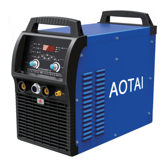
4-ATIG315/400/500 P/P-C 4-1 System components This series welding machine can be equipped with many different accessories and can be used in different special sites with different configurations. Fig. 4-1-1: System components 4-2 Basic equipments for welding Only be equipped with the necessary accessories, can the power source operate well. The following is the needed accessories list. -
Page 15: Control Panel
4-3 Control panel Note! You may find that your machine has certain functions or some parameters that are not described in this operating manual. Also, certain illustrations may be very slightly different from the actual controls on your machine.However, these controls function in exactly the same way. Fig. - Page 16 Fig. 4-3-5: 2-step operation mode 4-STEP operation mode Fig. 4-3-6: 4-step operation mode Repeat mode(only ATIG315/400/500P-C welding machine has this function,please refer to the sub menu) Fig. 4-3-7: Repeat mode...
- Page 17 Spot weld mode(only ATIG315/400/500P-C welding machine has this function,please refer to the sub menu) Fig. 4-3-8: Spot weld mode 2.CC/PULSE button on “TIG”: switch between “Constant” DC TIG and “Pulse” DC TIG;On “SMAW”: switch between “Amp” Display and “Volt” Display, the indicator will light up accordingly. 3.TIG/SMAW button press this button to switch between TIG and SMAW, the indicator will light up accordingly.
-
Page 18: Sub Menu
Parameters Description Unit Setting Factory range setting PRE-GAS Time of gas flow before welding 0.1~9.99 0.05 FLOW START The initial current after the arc is 5~315/400/ started UP-SLOPE Time of starting current is increased 0.1~10 until it reaches welding current HOT START Current of starting arc on SMAW 10-200... - Page 19 ATIG***P parameter Code Description Factory Setting P50 - no gas test function, Gas test function P50/P51 (First selection TIG mode) P51- gas test function Tungsten diameter P0.8-6.0 Tungsten diameter range P2.0 selection P0.8-P6.0 Table. 4-4-1: ATIG***P Sub menu parameters list ATIG***P-C Code Description...
-
Page 20: Other Function
Fig. 4-4-1: Sub menu operation Press and hold the selection knob and TIG/SMAW selection button at same time for 5 seconds to exit the sub menu interface. 4-5 Other function 4-5-1 Switch between gas cooling/water cooling mode When using water-cooling torch, press and hold the selection knob and adjustment knob at same time for 3 seconds, the machine will display "E0A"... -
Page 21: Interface
4-5-2 Gas test function In TIG mode, press the ‘parameter adjustment knob’ and ‘TIG/SMAW’ buttons at the same time for 5 seconds, the panel displays "GRS", perform the same operation to exit the gas test function. Fig. 4-5-2: Gas test function 4-5-3 Reset to factory setting Press and hold the selection knob and 2/4 step button at same time for 5 seconds to reset to factory setting (Fig. - Page 22 1.Output terminal (+) Connect electrode holder when in SMAW mode; Connect with the work piece when in TIG mode. 2.Control socket Connect to torch trigger. 3.Output terminal (-) Connect work piece when processing SMAW; connect with TIG torch when processing TIG welding.
-
Page 23: Installation
Pin No. Pin No. Description 38VAC 38VAC Table 4-6-2 Description of digital remote control socket 8.Fan Cooling down the heating components in the welding machine. 9. Water outlet 10 Gas inlet (part of solenoid valve) Connect with Argon gas regulator with gas hose. 11.Nameplate 12.Fuse 13.Circuit breaker... - Page 24 Please note the size of fuse and circuit breaker in the table below are for reference only. Model Power supply 3 phase, AC380/400/415V±10%, 50Hz Power grid Electricity grid min. power (KVA) Generator Fuse Input protection(A) Circuit breaker power cord ≥2.5 ≥4 ≥6 Output...
- Page 25 ●Gas cylinder installation 1.Stand the gas cylinder on the trolley and secure it by fixing the cylinder strap around a point in the top third of the cylinder-but never around the neck of the cylinder. 2.Take the protective cap off the gas cylinder. 3.Gently turn the gas-cylinder value anticlockwise, and blow off any dust and dirt.
- Page 26 ●TIG welding(water cooling) Fig. 4-7-4:Water-cooling TIG welding (Combined one machine) Fig. 4-7-5: Water-cooling TIG welding(Separate water cooling machine)
-
Page 27: Technical Data
●SMAW welding Fig.4-7-6:SMAW welding 4-8 Technical data Note! For machines designed for special voltages, below is the technical data on the name plate. Model Input voltage/frequency 3 phase, AC380V/400/415V, 50Hz Rated input capacity (KW) Rated input current (A) 21/20/19 28/26.6/25.6 38/36/34.7 Output current adjustment range (A) 4-510... -
Page 28: Dimension
4-9 Dimension Fig. 4-9-1: Dimension Item Unit(mm) Unit(inches) length 26.4 Width Height 22.5 Table. 4-9-1: Dimension... -
Page 29: Disassembly And Reassembly
4-10 Disassembly and reassembly Fig.4-10-1:Disassembly and reassembly... - Page 30 Stock No.for Item Stock No.for 500 Qty Remarks 315/400 Quick socket 740002-00026 740002-00026 Control socket 740003-00011 740003-00011 Quick socket 740002-00026 740002-00026 Breathing copper mouth 766001-00095 766001-00095 Output socket mounting plate 766003-02398 766003-02398 Plastic front panel 262005-01040 262005-01040 Front panel 262005-01039 262005-01039 Potentiometer knob 720031-00137...
- Page 31 746001-00101 746001-00019 415V electromagnetic valve 752001-00014 752001-00014 Back panel 262011-00738 262011-00738 Fuse holder 740007-00004 740007-00004 Circuit breaker cover 766003-02217 766003-02217 769001-00288 769001-00289 380/415V Cable 769001-00026 769001-00027 400V Control socket 740001-00184 740001-00184 Control socket 740003-00012 740003-00012 Fan cover 766003-02403 766003-02403 Right side panel 262023-00585 262023-00585 Bottom plate...
-
Page 32: 5-Remote Controller
Fast recovery diode module 735006-00029 735006-00029 Diode protection board 220455-00002 220455-00002 Exchange current inductance 220281-00008 220281-00008 Positive connection plate 766003-00399 766003-00399 Radiator connecting plate 775004-00033 775004-00027 Radiator support 766002-01112 766002-00078 Table.4-10-1: spare parts 5-REMOTE CONTROLLER 5-1 Analog remote controller The analog remote controller can only adjust the welding current, suitable for ATIG***P- C welding machine. -
Page 33: Digital Remote Controller
5-2 Digital remote controller Digital remote controller, can adjust various parameters of the welding machine panel, suitable for ATIG***P-C welding machine. Fig.5-2-1-1: Digital remote controller 5-2-1 Control panel Fig.5-2-2-1: control panel Please refer to chapter 4-3 of the control panel of the welding machine. 5-2-2 Interface Connect to welding machine. - Page 34 Pin No. Pin No. Description 38VAC 38VAC Null Table 5-2-2-1 Description of control socket 5-2-3 Spare parts Fig.5-2-3-1:Spare parts Item Stock No. Remarks Display board 220503-00075 Control socket 740001-00034 Control plug(7pin) 740001-00002 Control plug(6pin) 740003-00004 knob 720031-00066 PC sticker 771001-00658 Table.5-2-3-1 Description of control socket...
-
Page 35: 6-Trouble Shooting
6-TROUBLE SHOOTING Warning! An electric shock can be fatal. Before opening the machine: -Switch it off and unplug it from the mains -Unplug machine from the mains -Put up a clearly legible and easy-to-understand warning sign to stop anybody inadvertently switching it back on again -Check to make sure the electrically charged components (e.g.capacitors) have been discharged. - Page 36 Torch trigger No current output after pressing torch Release torch trigger fault trigger for 2s Shut down the welding The welding machine is over heat; Over-heat machine and wait for Temperature Relay fault protection cooling; or replace Main control board damaged Temperature Relay Water-cooling No circulating water in water cooling...
-
Page 37: 7-Care And Maintenance
7-CARE AND MAINTENANCE Before open the machine Warning! An electric shock can be fatal. Before opening the machine: Switch it off and unplug it from the mains -Put up a clearly legible and easy-to-understand warning sign to stop anybody inadvertently switching it back on again -Check to make sure the electrically charged components (e.g.capacitors) have been discharged -Bolts in outer case also work for ground connection.
Need help?
Do you have a question about the ATIG315P and is the answer not in the manual?
Questions and answers