Table of Contents
Advertisement
Quick Links
Advertisement
Table of Contents

Related Manuals for ASROCK ADLD4-P1


Summary of Contents for ASROCK ADLD4-P1
- Page 2 Version 1.0 Published June 2022 This device complies with Part 15 of the FCC Rules. Operation is subject to the following two conditions: (1) this device may not cause harmful interference, and (2) this device must accept any interference received, including interference that may cause undesired operation.
- Page 3 CALIFORNIA, USA ONLY The Lithium battery adopted on this motherboard contains Perchlorate, a toxic substance controlled in Perchlorate Best Management Practices (BMP) regulations passed by the California Legislature. When you discard the Lithium battery in California, USA, please follow the related regulations in advance. “Perchlorate Material-special handling may apply, see www.dtsc.ca.gov/hazardouswaste/ perchlorate”...
- Page 4 The terms HDMI® and HDMI High-Definition Multimedia Interface, and the HDMI logo are trademarks or registered trademarks of HDMI Licensing LLC in the United States and other countries. INTEL END USER SOFTWARE LICENSE AGREEMENT IMPORTANT - READ BEFORE COPYING, INSTALLING OR USING. LICENSE.
- Page 5 Licensee’s intellectual property rights, to incorporate or otherwise utilize those comments and suggestions. TERMINATION OF THIS LICENSE. Intel or the sublicensor may terminate this license at any time if Licensee is in breach of any of its terms or conditions. Upon termination, Licensee will immediately destroy or return to Intel all copies of the Software.
-
Page 6: Table Of Contents
Contents Chapter 1 Introduction Package Contents Specifications Motherboard Layout Front Panel Rear Panel Chapter 2 Installation Installing Memory Modules (SO-DIMM) Onboard Headers and Connectors Smart Switch M.2 WiFi/BT Module Installation Guide M.2 SSD Module Installation Guide (M2_1 and M2_2) Chapter 3 Auto Driver Installer Chapter 4 UEFI SETUP UTILITY Introduction 4.1.1... - Page 7 4.3.3 Storage Configuration 4.3.4 NVMe Configuration 4.3.5 ACPI Configuration 4.3.6 USB Configuration 4.3.7 Trusted Computing Hardware Health Event Monitoring Screen Tools Boot Screen Security Screen Exit Screen...
-
Page 8: Chapter 1 Introduction
ADLD4-P1 Chapter 1 Introduction Thank you for purchasing ADLD4-P1 motherboard. In this documentation, Chapter 1 and 2 contains the introduction of the motherboard and step-by-step installation guides. Chapter 3 contains the operation guide of the software and utilities. Chapter 4 contains the configuration guide of the BIOS setup. -
Page 9: Specifications
1.2 Specifications Platform • 7.0-in x 5.7-in, 17.8 cm x 14.5 cm • Supports 12 Gen Intel® Core Processors (Alder Lake-U) • 3 Power Phase design • Supports Intel® Hybrid Technology • Supports Intel® Turbo Boost Max 3.0 Technology Chipset • SOC Memory • Dual Channel DDR4 Memory Technology... - Page 10 ADLD4-P1 Audio • Realtek ALC269 Audio Codec • 1 x Headphone Jack • 1 x MIC-In • Gigabit LAN 10/100/1000 Mb/s • Giga PHY Intel® I219V • Supports Wake-On-LAN • Supports Lightning/ESD Protection • Supports Energy Efficient Ethernet 802.3az • Supports UEFI PXE Front • 1 x Power Button...
- Page 11 Connector • 1 x CPU Fan Connector (4-pin) • 2 x M.2 Fan Connectors (4-pin) BIOS • AMI UEFI Legal BIOS with multilingual GUI support Feature • ACPI 6.0 Compliant wake up events • SMBIOS 2.7 Support Hardware • CPU Temperature Sensing Monitor • CPU Fan Tachometer • CPU Quiet Fan (Auto adjust chassis fan speed by CPU...
-
Page 12: Motherboard Layout
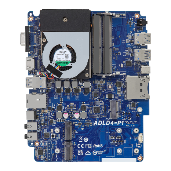
ADLD4-P1 1.3 Motherboard Layout Power Button USB 3.2 Gen2 T: USB_2 USB2.0 B: USB_1 USB 3.2 Gen2 T: USB_4 USB2.0 B: USB_3 TB_1 CPU_FAN1 USB 3.2 Gen2 T: USB_6 B: USB_5 SD Card BIOS RJ-45 DC Jack ADLD4-P1 Headphone Mic In... -
Page 13: Front Panel
1.4 Front Panel No. Description No. Description SD Card Socket USB 2.0 Port (USB_3) USB 4.0 Thunderbolt USB 3.2 Gen2 Type-A Port (USB_2) Type-C Port (TB_1) USB 2.0 Port (USB_1) USB 3.2 Gen2 Type-A Port Power Button (SW1) (USB_4) -
Page 14: Rear Panel
ADLD4-P1 1.5 Rear Panel No. Description No. Description D-Sub Port LAN RJ-45 Port* HDMI Port DC Jack USB 3.2 Gen2 Type-A Port Headphone Jack (USB_5_6) Microphone Input * There are two LEDs on each LAN port. Please refer to the table below for the LAN port LED indications. -
Page 15: Chapter 2 Installation
Chapter 2 Installation This is a Proprietary form factor motherboard. Before you install the motherboard, study the configuration of your chassis to ensure that the motherboard fits into it. Pre-installation Precautions Take note of the following precautions before you install motherboard components or change any motherboard settings. -
Page 16: Installing Memory Modules (So-Dimm)
ADLD4-P1 2.1 Installing Memory Modules (SO-DIMM) This motherboard provides two 260-pin DDR4 (Double Data Rate 4) SO-DIMM slots. It is not allowed to install a DDR, DDR2 or DDR3 memory module into a DDR4 slot; otherwise, this motherboard and SO-DIMM may be damaged. -
Page 17: Onboard Headers And Connectors
2.2 Onboard Headers and Connectors Onboard headers and connectors are NOT jumpers. Do NOT place jumper caps over these headers and connectors. Placing jumper caps over the headers and connectors will cause permanent damage to the motherboard. CPU Fan Connector This motherboard FAN_SPEED_CONTROL CPU_FAN_SPEED... -
Page 18: Smart Switch
ADLD4-P1 2.3 Smart Switch The motherboard has one smart switch: Power Button. Power Button Power Button allows users (SW1) to quickly turn on/off the (see p.7, No. 7) system. -
Page 19: Wifi/Bt Module Installation Guide
2.4 M.2 WiFi/BT Module Installation Guide The M.2 is a small size and versatile card edge connector that aims to replace mPCIe and mSATA. The M.2 Socket (Key E) supports type 2230 WiFi/BT module. * The M.2 socket does not support SATA M.2 SSDs. Installing the WiFi/BT module Step 1 Prepare a type 2230 WiFi/BT module... - Page 20 ADLD4-P1 Step 4 Tighten the screw with a screwdriver to secure the module into place. Please do not overtighten the screw as this might damage the module.
- Page 21 2.5 M.2 SSD Module Installation Guide (M2_1 and M2_2) The M.2 is a small size and versatile card edge connector that aims to replace mPCIe and mSATA. The Hyper M.2 Socket (M2_1, Key M), supports type 2260/2280 PCIe Gen4x4 (64 Gb/s) mode.
- Page 22 ADLD4-P1 M.2 SSD Module Support List Vendor Interface ADATA PCIe ADATA ASX7000NPC-512GT-C (XPG SX7000) (NVMe) ADATA PCIe ADATA ASX8000NPC-512GM-C (XPG ASX8000) (NVMe) Apacer PCIe Apacer Z280 AP240GZ280-240G (NVMe) Intel PCIe Intel Optane Memory 32GB (MEMPEK1W032GA)(NVMe) Intel PCIe Intel Optane Memory 16GB (MEMPEK1W016GA)(NVMe)
-
Page 23: Chapter 3 Auto Driver Installer
Chapter 3 Auto Driver Installer After you install the Windows OS and boot into the system, a notification will pop up to help you to install and update required drivers. -
Page 24: Chapter 4 Uefi Setup Utility
ADLD4-P1 Chapter 4 UEFI SETUP UTILITY 4.1 Introduction This section explains how to use the UEFI SETUP UTILITY to configure your system. You may run the UEFI SETUP UTILITY by pressing <F2> or <Del> right after you power on the computer, otherwise, the Power-On-Self-Test (POST) will continue with its test routines. -
Page 25: Navigation Keys
4.1.2 Navigation Keys Use < > key or < > key to choose among the selections on the menu bar, and use < > key or < > key to move the cursor up or down to select items, then press <Enter>... -
Page 26: Main Screen
ADLD4-P1 4.2 Main Screen When you enter the UEFI SETUP UTILITY, the Main screen will appear and display the system overview. The availability and location of BIOS settings can be different for different models and BIOS versions. System Date Use this item to specify the system date. -
Page 27: Advanced Screen
4.3 Advanced Screen In this section, you may set the configurations for the following items: CPU Configuration, Chipset Configuration, Storage Configuration, NVMe Configuration, ACPI Configuration, USB Configuration and Trusted Computing. Setting wrong values in this section may cause the system to malfunction. -
Page 28: Cpu Configuration
ADLD4-P1 4.3.1 CPU Configuration Intel Hyper Threading Technology Intel Hyper Threading Technology allows multiple threads to run on each core, so that the overall performance on threaded software is improved. Active Processor P-Cores Select the number of cores to enable in each processor package. - Page 29 Package C State Support Enable CPU, PCIe, Memory, Graphics C State Support for power saving. CFG Lock This item allows you to disable or enable the CFG Lock. C6DRAM Enable/Disable moving of DRAM contents to PRM memory when CPU is in C6 state.
-
Page 30: Chipset Configuration
ADLD4-P1 4.3.2 Chipset Configuration Above 4G Decoding Enable or disable 64bit capable Devices to be decoded in Above 4G Address Space (only if the system supports 64 bit PCI decoding). VT-d Intel® Virtualization Technology for Directed I/O helps your virtual machine... - Page 31 PCH PCIE ASPM Support This option enables/disables the ASPM support for all PCH PCIE devices. DMI ASPM Support This option enables/disables the control of ASPM on CPU side of the DMI Link. PCH DMI ASPM Support This option enables/disables the ASPM support for all PCH DMI devices. Share Memory Configure the size of memory that is allocated to the integrated graphics processor when the system boots up.
-
Page 32: Storage Configuration
ADLD4-P1 4.3.3 Storage Configuration SATA Controller(s) Enable/disable the SATA controllers. SATA Mode Selection AHCI: Supports new features that improve performance. Hybrid Storage Detection and Configuration Mode This item allows you select Hybrid Storage Detection and Configuration Mode. SATA Aggressive Link Power Management SATA Aggressive Link Power Management allows SATA devices to enter a low power state during periods of inactivity to save power. -
Page 33: Nvme Configuration
4.3.4 NVMe Configuration The NVMe Configuration displays the NVMe controller and Drive information. -
Page 34: Acpi Configuration
ADLD4-P1 4.3.5 ACPI Configuration Suspend to RAM Select disable for ACPI suspend type S1. It is recommended to select auto for ACPI S3 power saving. I219 LAN Power On Allow the system to be waked up by the Onboard Intel LAN. -
Page 35: Usb Configuration
4.3.6 USB Configuration XHCI Hand-off This is a workaround for OSes without XHCI hand-off support. The XHCI ownership change should be claimed by XHCI driver. -
Page 36: Trusted Computing
ADLD4-P1 4.3.7 Trusted Computing NOTE: Options vary depending on the version of your connected TPM module. Security Device Support Use this item to enable or disable BIOS support for security device. O.S. will not show Security Device. TCG EFI protocol and INT1A interface will not be available. - Page 37 NOTE: Your computer will reboot during restart in order to change State of the Device. Platform Hierarchy Use this item to enable or disable Platform Hierarchy. Storage Hierarchy Use this item to enable or disable Storage Hierarchy. Endorsement Hierarchy Use this item to enable or disable Endorsement Hierarchy. Physical Presence Spec version Select this item to tell OS to support PPI spec version 1.2 or 1.3.
-
Page 38: Hardware Health Event Monitoring Screen
ADLD4-P1 4.4 Hardware Health Event Monitoring Screen This section allows you to monitor the status of the hardware on your system, including the parameters of the CPU temperature, motherboard temperature, fan speed and voltage. CPU Fan 1 Setting Select a fan mode for CPU Fan 1, or choose Customize to set 5 CPU temperatures and assign a respective fan speed for each temperature. - Page 39 DRAM Voltage Use this to configure DRAM Voltage. The default value is [Auto].
-
Page 40: Tools
ADLD4-P1 4.5 Tools SSD Secure Erase Tool All the SSD's listed that supports Secure Erase function. NVME Sanitization Tool After you Sanitize SSD, all user data will be permanently destroyed on the SSD and cannot be recovered. Auto Driver Installer If Auto Driver Installer is enabled, a notification will pop up to help users to install and update required drivers after booting into the system. -
Page 41: Boot Screen
4.6 Boot Screen This section displays the available devices on your system for you to configure the boot settings and the boot priority. Fast Boot Fast Boot minimizes your computer's boot time. In fast mode you may not boot from an USB storage device. The VBIOS must support UEFI GOP if you are using an external graphics card. - Page 42 ADLD4-P1 Full Screen Logo Enable to display the boot logo or disable to show normal POST messages.
-
Page 43: Security Screen
4.7 Security Screen In this section you may set or change the supervisor/user password for the system. You may also clear the user password. Supervisor Password Set or change the password for the administrator account. Only the administrator has authority to change the settings in the UEFI Setup Utility. Leave it blank and press enter to remove the password. -
Page 44: Exit Screen
ADLD4-P1 4.8 Exit Screen Save Changes and Exit When you select this option the following message, “Save configuration changes and exit setup?” will pop out. Select [OK] to save changes and exit the UEFI SETUP UTILITY. Discard Changes and Exit When you select this option the following message, “Discard changes and exit...
Need help?
Do you have a question about the ADLD4-P1 and is the answer not in the manual?
Questions and answers