
Related Manuals for MTL MTL4500 Series


Summary of Contents for MTL MTL4500 Series
- Page 1 MTL合作伙伴:滨州新大新机电科技有限公司 MTL4500 Series isolating interface units Instruction Manual INM4500...
- Page 2 INM4500-2 Mar 2009...
-
Page 3: Table Of Contents
MTL4500 SERIES DESCRIPTION ........ - Page 4 ATEX If the country of installation is governed by the Essential Health and Safety Requirements (Annex II) of the EU Directive 94/9/EC [the ATEX Directive - safety of apparatus] then MTL document INA4500 must be consulted before installation. CERTIFICATION DATA The MTL web site http://www.mtl-inst.com contains product documentation regarding intrinsic...
-
Page 5: Introduction
Section 8 test procedures for all modules The MTL4500 concept The MTL4500 Series of modules and accessories is designed for use with process connected systems. It consists of compact isolating interface modules mounted on backplanes, which carry safe-area signals and power supplies. Hazardous-area circuits are connected to the terminals on the modules. Backplanes can be integrated into a user’s process system architecture or mounted in separate enclosures. -
Page 6: Standard Backplanes
Please contact MTL for further information. When mounting the back plane in Zone 2/Div 2 hazardous areas the MTL web site should be consulted for documents detailing any approvals. - Page 7 Table 4.1: Backplanes, mounting kits and accessories Mounting Kits Accessories Backplane Number Safe-area Surface DIN-rail 19-inch Earth-rail Tagging Spare model no. of modules connections (T or G) rack strip kit fuse pack CPS04 Screw-clamp SMS01 DMK01 – – – FUS08 CPS08 Screw-clamp SMS01...
-
Page 8: Backplanes - Identification And Tagging
4.1.2 T- or G-section DIN-rail mounting – with DMK01 mounting kit See Figures 4.1 and 4.2. Cut two pieces of T- or G-section DIN-rail to the required length and fi x them side-by-side with centres spaced appropriately – 132mm (CPS04), 113mm (CPS08/16) or 100mm (CPS24). With reference to Figure 4.4, clip the appropriate number of mounting feet (7) to the DIN rail (8) at centres ‘A’... - Page 9 Colour Module no. Function White MTL451x Digital Inputs MTL452x Digital Outputs MTL4541 Blue Analogue Inputs MTL4544 MTL4546 Green Analogue Outputs MTL4549 Orange MTL4575 Temperature inputs MODULE Grey MTL4599 Dummy isolator IDENT ERK08 BACKPLANE TSK08 IDENT Table 4.2: MTL4500 front label colour coding Figure 4.5: Locations for lables and attachments 4.2.2 Tagging strip mounting kit (TSK08, TSK16, TSK24) See Figures 4.1, 4.6.
-
Page 10: Backplanes - Earth Rails
Backplanes - earth rails Optional earth rails are available for 8- and 16-way backplanes (kits ERK08 and ERK16 respectively). Cable screens from hazardous-area circuits, or spare pairs from a multicore cable, can be connected to the terminals on the earth rails, which are mounted on the backplane at about the same height as the front of the modules, close to the hazardous-area connectors. -
Page 11: Backplanes - Customised
The rating of the fuse is:– 24-way: 3.15A (FUS24 fuse kit) Backplanes – customised For information about installing customised backplanes (whether supplied by MTL or by a third party), see the separate instructions provided with the units. INM4500-2 Mar 2009... -
Page 12: Installation - Modules
10mA at ≥ 5V is recommended. 5.1.4 Earth leakage detection An MTL4220 earth leakage detector can be used with a number of MTL4500 Series units to detect hazardous-area earth faults which can then be rectified without needing to shut down the loop ('no-fail' operation). -
Page 13: Modules - Installation
5.1.5 Ambient temperature considerations Ambient temperature limits for unenclosed MTL4500 Series isolators are from –20°C to +60°C with units close-packed. Modules - installation 5.2.1 Signal conductors Removable blue hazardous area signal plugs, located on the front of the modules, are mechanically keyed to fi... -
Page 14: Unit Descriptions, Setting-Up And Connections
MTL web site at http://www.mtl-inst.com or in the current MTL IS catalogue. If a fault is suspected, first check that the power LED is lit (not applicable to loop-powered devices). If necessary, check that all signal and power plugs are properly inserted, that no wires are loose and that the unit is mounted correctly. -
Page 15: Digital Input Modules
Digital Input modules The Digital Input (DI) module range offers solid state or relay output switches in a safe area that respond to input switches located in a hazardous area. Single or multiple channel (2 or 4) options are available, as well as Line Fault Detecion (LFD). -
Page 16: Mtl4510 & Mtl4510B - Switch/Proximity Detector Interface
6.1.2 MTL4510 & MTL4510B - Switch/Proximity detector interface 4-channel digital input and multifunction modules These digital modules provide solid state output switches in a safe area that respond to switches (inputs) located in a hazardous area. The way they respond - their “mode” - can be configured using a bank of four DIL selector switches accessible through the side of the module - see Figure 6.2. - Page 17 Figure 6.2 DIL switches for setting MODE 1 2 3 4 OFF position ON position For ease of access, it is recommended that switches are set to the required mode before installation. Table 6.1 indicates whether the output follows the input, or the output is the reverse or antiphase of the input.
- Page 18 MTL4510B modes The following logic and timing diagrams are provided to assist the user in understanding the behaviour of the MTL4510B module when a specific mode is chosen. The open switch ( ) and closed switch ( ) symbols are used to represent both the input conditions of Ch A, Ch B, Ch C or Ch D and then the output conditions of o/p 1, 2, 3 or 4.
- Page 19 MTL4510B modes - continued Mode 9 Mode 10 i/p - Ch A i/p - Ch A Line Line Line Line fault fault fault fault fault fault fault fault o/p 1 o/p 1 i/p - Ch C i/p - Ch C Line Line Line...
-
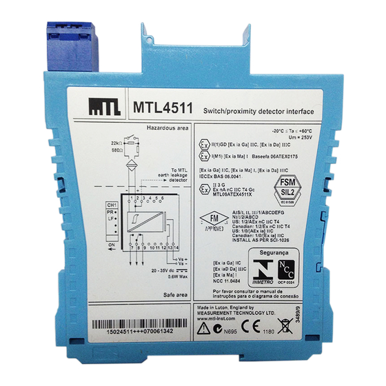
Page 20: Mtl4511 - Switch/Proximity Detector Interface
Note: Signal plug HAZ1-3 is required for access to the earth leakage detector function. Hazardous area Switch-type sensors 22kW require resistors 680W if LFD is selected To MTL earth leakage detector – 1 2 3 4 5 6 7 8 9 10 1112 13 14 20–35V dc MTL4511 Vs–... -
Page 21: Mtl4513 - Switch/Proximity Detector Interface
Switch-type sensors 22kW 22kW require resistors 680W 680W if LFD is selected Ch 1 Ch 2 To MTL earth leakage detector – – 1 2 3 4 5 6 7 8 9 10 1112 13 14 20–35V dc MTL4513 Vs–... -
Page 22: Mtl4514 - Switch/Proximity Detector Interface
Note: Signal plug HAZ1-3 is required for access to the earth leakage detector function. Hazardous area Switch-type sensors 22kW require resistors 680W if LFD is selected To MTL earth leakage detector – 1 2 3 4 5 6 7 8 9 10 1112 7 8 9 10 1112 13 14 13 14 20–35V dc... -
Page 23: Mtl4516 - Switch/Proximity Detector Interface
Switch-type sensors 22kW 22kW require resistors 680W 680W if LFD is selected Ch 1 Ch 2 To MTL earth leakage detector – – 1 2 3 4 5 6 7 8 9 10 1112 13 14 20–35V dc Vs– MTL4516... -
Page 24: Mtl4516C - Switch/Proximity Detector Interface
Switch-type sensors 22kW 22kW require resistors 680W 680W if LFD is selected Ch 1 Ch 2 To MTL earth leakage detector – – 1 2 3 4 5 6 7 8 9 10 1112 13 14 20–35V dc Vs– MTL4516C... -
Page 25: Mtl4517 - Switch/Proximity Detector Interface
22kW require resistors 680W 680W if LFD is selected Ch 1 Ch 2 To MTL earth leakage detector – – 1 2 3 4 5 6 7 8 9 10 1112 7 8 9 10 1112 13 14 13 14 20–35V dc... -
Page 26: Digital Output Modules
Note: Signal plug HAZ1-3 is required for access to the earth leakage detector function. Hazardous area Solenoid, alarm or other IS device To MTL earth leakage detector – + 1 2 3 4 5 6 7 8 9 10 1112 13 14 Vs–... -
Page 27: Mtl4523/Mtl4523R - Solenoid Alarm Driver
Note: Signal plug HAZ1-3 is required for access to the earth leakage detector function. Hazardous area Solenoid, alarm or other IS device To MTL earth leakage detector – + 1 2 3 4 5 6 MTL4523 7 8 9 10 1112 13 14 + –... -
Page 28: Mtl4523L - Solenoid Alarm Driver
Note: Signal plug HAZ1-3 is required for access to the earth leakage detector function. Hazardous area Solenoid, alarm or other IS device To MTL earth leakage detector – + 1 2 3 4 5 6 7 8 9 10 1112 13 14 –... -
Page 29: Mtl4524 - Solenoid Alarm Driver
Note: Signal plug HAZ1-3 is required for access to the earth leakage detector function. Hazardous area Solenoid, alarm or other IS device To MTL earth leakage detector – + 1 2 3 4 5 6 7 8 9 10 1112 13 14 20–35V dc... -
Page 30: Mtl4524S - Solenoid Alarm Driver
Note: Signal plug HAZ1-3 is required for access to the earth leakage detector function. Hazardous area Solenoid, alarm or other IS device To MTL earth leakage detector – + 1 2 3 4 5 6 7 8 9 10 1112 13 14 20–35V dc... -
Page 31: Mtl4525 - Solenoid Alarm Driver
Note: Signal plug HAZ1-3 is required for access to the earth leakage detector function. Hazardous area Solenoid, alarm or other IS device To MTL earth leakage detector – + 1 2 3 4 5 6 7 8 9 10 1112 13 14 20–35V dc... -
Page 32: Mtl4526 - Switch Operated Relay
6.2.8 MTL4526 - Switch operated relay Two channel, IS output The MTL4526 enables two separate IS circuits in a hazardous area to be relay-contact controlled by two on-off switches or logic signals in a safe area. Applications include the calibration of strain–gauge bridges;... -
Page 33: Analogue Input Modules
Analogue Input modules The analogue input (AI) modules support 2-wire or 3-wire 4/20mA or ‘smart’ transmitters located in a hazardous area; repeating the current in other circuits to drive safe-area loads. 6.3.1 MTL4541 - Repeater Power Supply 4/20mA smart for 2- or 3-wire transmitters The MTL4541 provides a fully-fl... -
Page 34: Mtl4541B/4541P - Repeater Power Supply
6.3.2 MTL4541B/4541P - Repeater Power Supply 4/20mA smart for 2- or 3-wire transmitters Each of the MTL4541B and MTL4541P modules provides a fully-fl oating dc supply for energising a conventional 2- or 3-wire 4/20mA transmitter that is located in a hazardous area, and repeats the current in another circuit to drive a safe-area load. -
Page 35: Mtl4544 - Repeater Power Supply
6.3.3 MTL4544 - Repeater Power Supply 4/20mA smart for 2- or 3-wire transmitters The MTL4544 provides fully-fl oating dc supplies for energising two conventional 2-wire or 3-wire 4/20mA or ‘smart’ transmitters located in a hazardous area, and repeats the current in other circuits to drive two safe-area loads. -
Page 36: Mtl4544B - Repeater Power Supply
6.3.4 MTL4544B - Repeater Power Supply 4/20mA smart for 2- or 3-wire transmitters The MTL4544B provides fully-fl oating dc supplies for energising two conventional 2-wire or 3-wire 4/20mA or ‘smart’ transmitters located in a hazardous area, and repeats the current in other circuits to drive two safe-area loads. -
Page 37: Analogue Output Modules
Analogue Output modules The analogue output (AO) modules accept 4/20mA floating signals from safe-area controllers to drive current/pressure converters (or any other load up to 800Ω) in a hazardous area. 6.4.1 MTL4546/4546C/4546Y - Isolating Driver For 4/20mA smart valve positioners with line fault detection The MTL4546 accepts a 4/20mA fl... -
Page 38: Mtl4549/4549C/4549Y - Isolating Driver
6.4.2 MTL4549/4549C/4549Y - Isolating Driver Two channel, for 4/20mA smart valve positioners with line fault detection The MTL4549 accepts 4/20mA fl oating signals from safe-area controllers to drive 2 current/pressure converters (or any other load up to 800Ω) in a hazardous area. For smart valve positioners, the module also permits bi-directional transmission of digital communication signals so that the device can be interrogated either from the operator station or by a hand-held communicator. -
Page 39: Temperature Input Module
Temperature Input module The MTL4575 module accepts inputs from low-level dc sources such as thermocouples or RTDs in hazardous areas and converts them into 4/20mA signals to drive safe area loads. 6.5.1 MTL4575 - Temperature Converter THC or RTD input with alarm The MTL4575 converts a low-level dc signal from a temperature sensor mounted in a hazardous area into a 4/20mA current for driving a safe-area load. - Page 40 6.5.2 Modules – setting and confi guration Before an MTL4575 module can be used it must be configured for the intended application. Unless ordered differently, every MTL4575 module is supplied with the following default configuration. Default Configuration Input type Type K thermocouple Linearisation enabled Units...
-
Page 41: General Modules
These are general purpose modules that have applications associated with the MTL4500 range of modules. 6.6.1 MTL4599 - Dummy Isolator The primary function of the MTL4599, which can be used with all other MTL4500 Series units, is to provide termination and earthing facilities for unused cable cores from hazardous areas. Hazardous area... -
Page 42: Pcs45/Pcl45Usb Configurator For Mtl Temperature Converters
5 to 95% relative humidity (non-condensing) Weight 200g PCS45 Confi guration software Compatible with Windows 2000 or Windows XP. Consult MTL for operation with any other operating system, e.g. Windows Vista™. Software medium PCS45 supplied on CD Updates are available at www.mtl-inst.com... - Page 43 Safety It is not permitted to connect the PCL45USB to any device other than one approved by MTL. Authorisation is valid provided that the converter type is named on the PCL45USB certifi cate or if the PCL45USB is specifi ed on the converter certifi cate. Repairs to the PCL45USB are not permitted.
-
Page 44: Bench Testing Modules
Field units that do not perform as described below, or modules that have ‘unusual’ operating behaviour, should be replaced and returned to MTL. Consult individual module wiring diagrams for terminal connections. -
Page 45: Digital Output (Do) Modules
Digital Output (DO) modules Apply tests per channel. 7.2.1 Loop powered: - MTL4521 & 4525 Vs– Figure 7.2 Loop powered – DO test circuit Connect a voltmeter between the + & – output terminals of the module, observing polarity. Apply 24V between the supply terminals (Vs+, Vs–) The voltmeter should indicate a value between 21.4 and 24 volts Switch off the power to the module Connect an ammeter between the + &... -
Page 46: Analogue Input (Ai) Modules
Analogue Input (AI) Modules 7.3.1 Modules: All variants This test compares the output current with the input current over the normal range of operation. Input Conditions Connect the channel output to the channel input (+ to –, and – to +) as shown below. Note: Do not connect a voltmeter in circuit to measure V1 until requested in Step 4 below, because current measurement A2 could be affected. -
Page 47: Testing The Functioning Of Other Modules
Simple tests can be devised for other modules (e.g. temperature, pulse, vibration, etc) to verify their operation. If any assistance is required for the testing of a particular module, please contact the technical support department at MTL for advice. INM4500-2... -
Page 48: Applications Involving Zone 2 And/Or Zone 22 Hazardous Areas
(Note: The IEC standards are considering Equipment Protection Level [EPL] marking but at this stage this will not be introduced on MTL products. The situation will be reviewed as the standard writing process becomes more defi nitive.) In general, meeting the relevant requirements of the appropriate European (CENELEC) standards is considered the most appropriate method of demonstrating compliance with the ATEX directive. - Page 49 INM4500-2 Mar 2009...
- Page 50 INM4500-2 Mar 2009...
- Page 51 INM4500-2 Mar 2009...
- Page 52 4001 W. Sam Houston Parkway N., Suite 150 Tel: + 91 (0)44 24501660/24501857 Fax: + 91 (0)44 24501463 Houston TX 77043 E-mail: sales@mtlindia.com Tel: +1 281 571 8065 Fax: +1 281 571 8069 E-mail: info@mtl-inst.com Group Internet home page http://www.mtl-inst.com/ Members of The MTL Instruments Group...
Need help?
Do you have a question about the MTL4500 Series and is the answer not in the manual?
Questions and answers