
Subscribe to Our Youtube Channel
Summary of Contents for Kongsberg RSER200-4
- Page 1 RSER200-4 Hardware Module Description Kongsberg Maritime Part no.603444 300993/Ap27 October 2006...
- Page 2 Kongsberg Maritime AS. Kongsberg Maritime AS endeavours to ensure that all information in this document is correct and fairly stated, but does not accept liability for any errors or omissions.
-
Page 3: Table Of Contents
Hardware Module Description Table of contents Glossary........................4 OVERVIEW................ 5 Document user......................5 Module........................5 FUNCTION ................ 6 Power supply input ....................6 Serial Line Interfaces....................7 2.2.1 Link Channel interfaces................. 8 2.2.2 Field Channel interfaces ................8 2.2.2.1 RS232 typical ..................8 2.2.2.2 RS422 typical ..................9 2.2.2.3 RS485 typicals.................. -
Page 4: Glossary
Mean Time Between Failure NMEA National Marine Electronics Association Protective Earth RIO200 Kongsberg Maritime Remote I/O 200 module family RBUS Remote I/O Bus that covers both communication link and power RBUS Power Electrical power supply to the RIO200 modules including Þeld... -
Page 5: Overview
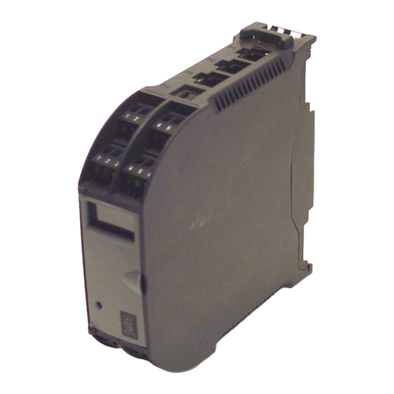
Physical interfaces and capabilities are described. 1.2 Module The RSER200-4 is a module in the Kongsberg RIO200 module family. These modules provide functions such as I/O interface, network hub/repeater and serial line interface. They have the same shape and are mechanically mounted on a horizontal dual-rail system. -
Page 6: Function
Kongsberg RSER200-4 2 FUNCTION Figure 1 RSER200-4 function diagram The RSER200-4 is a serial line module used for connecting serial line equipment to RCU(s) in single or redundant controller systems. The module can be connected to up to three controllers (A, B, C) via the three RJ45 connectors (P1, P2, P3), and up to four Þeld... -
Page 7: Serial Line Interfaces
The illustration in Þgure below shows the switching principles of RSER200-4. One controller (A, B or C) can send serial data via one RSER200-4 module to four serial line Þeld channels. This is achieved by de-multiplexing. Dual or triple redundant controllers can be connected to the module. -
Page 8: Link Channel Interfaces
(P3) are available. Each Link Channel interface is connected using a cable connection between one dedicated RJ45 connector on the RCU and one of the RJ45 connectors P1, P2, and P3 on RSER200-4. The Link Channel interfaces are implemented with high speed RS422. 2.2.2 Field Channel interfaces Four isolated, identical, serial line Þeld channels 1, 2, 3 and... -
Page 9: Rs422 Typical
Function 2.2.2.2 RS422 typical Figure 5 RS422 interface typical 2.2.2.3 RS485 typicals Figure 6 RS485 interface typical, 3 wires 300993/Ap27... -
Page 10: Nmea 0183 Typical
Kongsberg RSER200-4 Figure 7 RS485 interface typical, 6 wires 2.2.2.4 NMEA 0183 typical Figure 8 NMEA 0183 interface typical 2.3 LED indicators The module front is provided with several LEDs on the module front. The LED layout is shown on Figure 9 on page 11... - Page 11 Function Figure 9 LED indicators layout Table 1 LED indicators on module front Colour, state Function name Status Green, Þxed Normal operation. The module is OK and it has communication with at least one RCU Red, Þxed Serious HW or SW error condition occurred, watchdog activated Red, ßashing During boot...
-
Page 12: Usb Interface
Kongsberg RSER200-4 2.4 USB interface A USB port (USB 2.0, full speed, 12 Mbit) is included on the module to facilitate direct communication with the module controller for test and service purposes. The interface uses a USB B type connector (P4) and is protected by a transient suppressor. -
Page 13: Technical Specifications
Technical speciÞcations 3 TECHNICAL SPECIFICATIONS Table 2 Technical speciÞcations Power speciÞcations Input voltage +24 VDC nominal (+18 - +32 VDC) Power ON rise time Maximum 20 ms/V monotonic Current consumption 50 mA Power ON inrush current Maximum 0.5 A Link Channels Bit rate 1 Mbps 100 m... -
Page 14: Configuration
Kongsberg RSER200-4 4 CONFIGURATION The illustration below shows the layout of the RSER200-4 module. Figure 10 Layout of RSER200-4 The following sections describe the module label layout, and the connectors’ layout and pin allocation. 300993/Ap27... -
Page 15: Module Identiþcation
4.1 Module identiÞcation There is a module identiÞcation label on each module. For any communication with Kongsberg Maritime on this module you should refer to the part number (Part#), revision (Rev.) and serial number (Serial#). The information is also available from the system. -
Page 16: P4 - Usb Connector
Kongsberg RSER200-4 4.3 P4 - USB connector This connector i an USB type B, 6 pin, shielded. Table 4 USB B pin allocation Name Pin no. Function +5 VDC from host computer USB_D- USB Transceiver Data Low USB_D+ USB Transceiver Data High... -
Page 17: Rbus A And Rbus B Connector
ConÞguration where n = 1 for X1, 2 for X2, 3 for X3, 4 for X4 4.5 RBUS A and RBUS B connector The two RBUS A and RBUS B connectors are of type 5-pole Phoenix T-BUS™ connectors. They are located on the dual-rail and provides RBUS Power connections. -
Page 18: Installation
Open the module front door. Label the module with the appropriate module name. Hook the RSER200-4 on to the lower DIN rail in a 30° angle and snap it to the RBUS connectors and upper DIN rail in one rotating movement. -
Page 19: Replacement
Replacement 6 REPLACEMENT Caution The module can be unpacked and handled without ESD protection, but electrostatic discharge can damage components on the module when terminating wires and cables to it. Therefore always wear a correctly-connected earthing strap when working on the module. Remove the terminal block headers on X1 to X4 that are in use (the ones with wires attached). - Page 20 ßat-bladed screwdriver and jack them out, one by one. Hook the RSER200-4 on to the lower DIN rail in a 30° angle and snap it to the RBUS connectors and upper DIN rail in one rotating movement.
- Page 21 1 to 4. 10 If power is OFF, turn ON power. The module status LED will be lit red initially during start-up. The module status LED will be lit green when the RSER200-4 communication with a controller (RCU) is established. 300993/Ap27...
- Page 22 2006 Kongsberg Maritime © Kongsberg Maritime AS P.O.Box 483 Telephone: +47 32 28 50 00 N-3601 Kongsberg, Telefax: +47 32 28 50 10 Norway Service: +47 815 35 355 www.kongsberg.com...
Need help?
Do you have a question about the RSER200-4 and is the answer not in the manual?
Questions and answers
On RSER200-4 orange led lit in left corner where label can be added, meaning of it. Thank you
Self test error on RSER200 module, How to reset