Table of Contents
Advertisement
Quick Links
Advertisement
Chapters
Table of Contents

Related Manuals for TK TW45C

Summary of Contents for TK TW45C
- Page 1 OPERATING MANUAL TW45C Drive 06/2022 6231003860...
- Page 2 The choice of colours used in our documents for the components is solely for illustration purposes in the documentation! You can find out about the colours for your products from your TK Aufzug- swerke GmbH sales partner. Form of address In the interest of better legibility, we use exclusively the masculine grammat- ical form, for example "fireman".
-
Page 3: Table Of Contents
4.1.10 Gear efficiency.............................. 45 4.1.11 Mass moment of inertia............................ 45 Dimensions................................. 46 4.2.1 Machine room version / vertical motor position.................. 46 4.2.2 Machine room version / horizontal motor position.................. 47 TK Elevator BA, TW45C | 6231003860 | 06/2022... - Page 4 Verification of traction sheave calculation.................... 86 10.2.3 mayr ROBA-duplostop Size 125 brake - installation and operating manual.......... 87 10.2.4 mayr ROBA-duplostop Size 500 - 1800 brake - installation and operating manual...... 103 10.2.5 SKINTOP MS-SC Mounting instructions....................... 119 TK Elevator BA, TW45C | 6231003860 | 06/2022...
- Page 5 Drehgeber Wachendorf WDG 100H-25-1024 - Datenblatt............... 126 10.2.9 Drehgeber Wachendorf WDG 100H-XX-YYYY - Datenblatt.pdf.............. 138 10.2.10 Drehgeber Wachendorf WDG 100H-38-1024 - Datenblatt.pdf............... 140 10.2.11 Drehgeber Wachendorf WDG 100H-XX-YYYY - Montageanleitung............ 141 10.2.12 Drehgeber Wachendorf WDG 100H-38-2048.pdf.................. 142 TK Elevator BA, TW45C | 6231003860 | 06/2022...
-
Page 6: About These Instructions
Reference Chap. 1, P. 6 List ▪ Top item of a list – Sub-item of a list – Sub-item of a list ▪ Top item of a list ▪ Top item of a list TK Elevator BA, TW45C | 6231003860 | 06/2022... -
Page 7: Safety
Read and comply with the warning. 2.1.3 Indication of possible damage to property NOTICE Hazard with possible damage to property! May lead to product function impairments or function loss. Read and comply with the warning. TK Elevator BA, TW45C | 6231003860 | 06/2022... -
Page 8: Safety Requirements
Clearly establish all areas of responsibility prior to any activity. Always wear the personal protective equipment made available to you. Prior to work, make people aware of the dangers of electrical current. TK Elevator BA, TW45C | 6231003860 | 06/2022... -
Page 9: Dangers In Handling The Drive
▪ The elevator installation must ensure that emergency braking by the mechanical brake system takes place in the following cases: – Uncontrolled movement out of the stopping zone TK Elevator BA, TW45C | 6231003860 | 06/2022... -
Page 10: Warranty And Liability
2.3.1 Structural modification of the product The product is configured in the factory and delivered ready for operation. If changes are made to the product, the entire warranty of TK Aufzugswerke GmbH shall become null and void. 2.3.2 Use in line with intended use The product has been constructed using state-of-the-art technology and in line with the recognised technical safety regulations. -
Page 11: 10 Rules For Health And Safety At Work
10 rules for health and safety at work 10 rules for health and safety at work The international rules for occupational health and safety can also be found https://eli.tkelevator.com/sup- on our internet platform ELI for download at: port/occupational-safety-health TK Elevator BA, TW45C | 6231003860 | 06/2022... -
Page 12: Personal Protective Equipment
▪ Flying parts ▪ Flying particles Eye injury Protective ▪ Laser beams goggles Loss of sight/blinding ▪ Emissions of optical rays Enable ▪ Electrical voltage Electric shock source of en- ergy TK Elevator BA, TW45C | 6231003860 | 06/2022... -
Page 13: Description
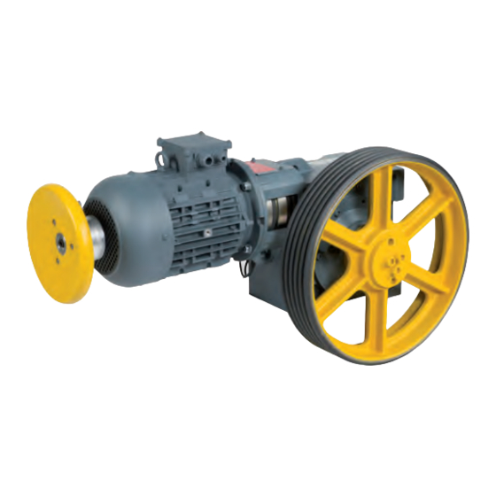
The TW45C has been available since May 2011 and it differs from the previous version TW45B in that there are modified anti-friction bearings with optimised sealing (stroke unit on worm shaft). - Page 14 ▪ ISIS1 version: Horizontal motor position; traction sheave position on left / on right, with emergency brake system, NBS – for machine location in the shaft pit. The machine is exclusively available with frequency-controlled motors (V3F). TW45C in horizontal version for installation in the machine room Fig. 1 ATR_2_21_0027_0 Item Designation...
- Page 15 Oil level monitoring (gauge (R3/4") glass) Motor connection (M16x1.5 / M25x1.5) Traction sheave mounting (ten- sion disc with screwed connec- Brake connection tion) (2x M16x1.5) Machine base frame mounting 13 Transport eyebolts surface (foot mounting) TK Elevator BA, TW45C | 6231003860 | 06/2022...
- Page 16 Oil level monitoring (gauge (R3/4") glass) Motor connection (M16x1.5 / Traction sheave mounting (ten- M25x1.5) sion disc with screwed connec- tion) Brake connection (2 M16x1.5) Machine base frame mounting 13 Transport eyebolt surface (foot mounting) TK Elevator BA, TW45C | 6231003860 | 06/2022...
- Page 17 NBS Socket wrench for manual re- Screws for manual release lease (screw head marked in red) Brake test switch with connec- Connection line, brake voltage tion line Protective cover for brake TK Elevator BA, TW45C | 6231003860 | 06/2022...
- Page 18 Machine room with earthquake safeguard complying with EN81-77 (shown in the left traction sheave position / vertical motor position and earthquake safeguard complying with EN81-77) Fig. 6 ATR_2_12_0106_0 TK Elevator BA, TW45C | 6231003860 | 06/2022...
- Page 19 / flange mounting sur- Traction sheave (D360) face) Motor (version with terminal box Operational brake Warner for connection of the opera- SZ50/50 (2x50 Nm), including 6 tional brake) m connection line TK Elevator BA, TW45C | 6231003860 | 06/2022...
- Page 20 520 / 590) face) Operational brake Warner Motor (connection box at side) SZ50/50 (2x50 Nm), including 6 m connection line Motor connection (M16x1.5 / Actual-value sensor M25x1.5) Transport eyebolt Oil drain (R3/4") TK Elevator BA, TW45C | 6231003860 | 06/2022...
- Page 21 Machine in the shaft pit (foot mounting) Fig. 10 ATR_2_21_0033_0 Item Designation Item Designation Driving gear (horizontal motor Traction sheave (D360, D440, position / foot mounting sur- D520/590) face) Operational brake Warner SZ50/50 (2x50 Nm), including Motor connection line TK Elevator BA, TW45C | 6231003860 | 06/2022...
- Page 22 110 / 55 V DC. Both brakes have CSA certification. The operational brake with 2x50 Nm is regarded as a 100 Nm brake (ASME A17.1) for this use case. TK Elevator BA, TW45C | 6231003860 | 06/2022...
-
Page 23: Engineering Design
2-circuit disc brakes with an integrated elastic dog clutch (plug-in type) for the connection of motor and worm shaft. The brake TW45C is intended for static application as a parking brake. Dy- namic braking is restricted to emergency and inspection braking. -
Page 24: Machine Base Frame
- counterweight ASL ≤ (DT + 100) mm with traction sheave diameter 520 or 590 mm ▪ Installations with rope suspension 2:1 and traction sheave diameters 360, 440, 520 or 590 mm TK Elevator BA, TW45C | 6231003860 | 06/2022... - Page 25 The rope pulleys (versions, see product description of rope pulleys) are designed with maintenance-free roller bearings. Fig. 13 ATR_2_21_0040_0 Item Designation Item Designation TW45B M SR machine base TW45C machine frame Mounting parts for machine Insulation elements base frame TK Elevator BA, TW45C | 6231003860 | 06/2022...
- Page 26 A set of screwed connection elements (M16 - 8.8) is available for mounting the TW45C machine on the machine base frame TW45B O SR / M SR. A modified mounting (4 x M16-10.9 – 190 Nm) is required for TW45C machine use cases with horizontal or vertical upward rope departure - except for the housing with flange mounting.
- Page 27 The protection device consists of a modified rope guard for rope pulleys of diameter D360 or D450 which prevent the ropes departing from the grooves. Fig. 16 ATR_2_12_0156_0 TK Elevator BA, TW45C | 6231003860 | 06/2022...
-
Page 28: Encoder
In the case of the ISIS1 version, the position of the motor terminal box is gen- erally at the side opposite the traction sheave. The specified electrical data apply to the following site conditions: TK Elevator BA, TW45C | 6231003860 | 06/2022... -
Page 29: Gear Unit
The standard version of the encoders (for description and technical data, see product catalogue for elevator motors) include a 10-metre long connection cable, including connectors (types 1024/4096 TTL) for connection to TK El- evator frequency inverters and/or free cable ends with wire end ferrules (type 1024 HTL and type 1024 sine/cosine). -
Page 30: Machine Versions
Machine versions Standard version for machine location in the machine room In the standard version for deployment in the machine room, the TW45C ma- chine consists of the components: ▪ Driving gear (including oil filling) with foot mounting surface for hori- zontal / vertical motor position ▪... - Page 31 The emergency brake is activated via a separate control unit including ter- minal box and connecting lines as well as an additional safety switch at the overspeed governor (TK Elevator) to activate the facility in the event of over- speed (not for ISIS1 version).
- Page 32 The rope guard is designed in such a way that all standard gaps between the ropes on the rope departure can be covered with the TW45B O SR and TW45B M SR base frames. TK Elevator BA, TW45C | 6231003860 | 06/2022...
- Page 33 As gear ratios, the versions 40:3 and 32:3 are intended. The versions EMOD 5.5 / 7.5 and 11 kW in voltage interchangeable version 230 / 460 V are de- ployed as motors. TK Elevator BA, TW45C | 6231003860 | 06/2022...
-
Page 34: Combination Of Versions / Options
C 5.2 / 7.0 kW versions - motor CEG / E 5.5 / 7.5 /. 11.0 kW versions - motor EMOD TWR machine location - machine room SK machine location – shaft headroom / shaft pit Machine location - shaft pit TK Elevator BA, TW45C | 6231003860 | 06/2022... - Page 35 440 / 520 / 590 / 360 / 320 Versions - traction sheave NBS Version with emergency brake-NBS RSZ125 or SZ50/50 Version of operational brake EN81-77 Version with earthquake protection in accordance with EN81-77 ISIS1 Delivery version for ISIS1 / SA1 version with modified fastening TK Elevator BA, TW45C | 6231003860 | 06/2022...
-
Page 36: Technology
105 Tab. 2 ATR_1_21_0005_0 4.1.2 Performance chart for standard applications vrated Q´max F´max 0.50 1000 0.50 1250 0.63 1070 0.63 46:1 1600 1350 0.80 0.80 1190 1100 1390 32:1 1.00 1.00 1180 TK Elevator BA, TW45C | 6231003860 | 06/2022... - Page 37 1050 1350 1740 1200 1300 1420 41:2 1350 1050 0.80 1210 0.80 1350 1130 40:3 1200 1600 1500 1060 41:2 1400 40:3 1050 1500 1300 1780 1.00 41:2 1.00 1400 1510 1250 TK Elevator BA, TW45C | 6231003860 | 06/2022...
-
Page 38: Performance Chart For Applications In The Isis1
(e.g. TLD) to check the op- erational safety of the machine. The machines are conceived for a service life of at least 15 years and/or 20,000 hours of operation. TK Elevator BA, TW45C | 6231003860 | 06/2022... -
Page 39: Brake
2-surface disc brake (2 mechanical brake circuits with a joint electro- Design magnetic circuit for release) Brake linings Asbestos-free Brake disc diameter [mm] Air gap [mm] 0.5 +0.25 Air gap setting Not possible TK Elevator BA, TW45C | 6231003860 | 06/2022... - Page 40 1 magnetic clamp with armature base plate Operating voltage [VDC] 207 / 104 110 / 55 Overexitation / holding voltage Operating current 1.7 / 0.85 3.28 / 1.64 Overexitation / holding current TK Elevator BA, TW45C | 6231003860 | 06/2022...
-
Page 41: Traction Sheave
With minimum groove clearance - RAmin - in accordance with product description for groove profiles for seat grooves (for vee groove, if deviating). TKE-NA provides a D267 mm traction sheave for the ISIS1 (MRL) version (not in the scope of supply of TK Aufzugswerke GmbH). TK Elevator BA, TW45C | 6231003860 | 06/2022... -
Page 42: Motor Versions
[mm] Weight [kg] Actual-value sensor WDG100-38-1024/4096 TTL (standard) Actual-value sensor WDG100-38-1024 HTL / (special) WDG100-38-1024 sine/cosine Tab. 10 ATR_1_21_0034_0 1) Optionally without handwinding wheel with machine location in the shaft headroom/shaft pit. TK Elevator BA, TW45C | 6231003860 | 06/2022... -
Page 43: Load Data - Traction Sheave Shaft
There are restrictions for Ft for the rope departure directions horizontal and vertical upwards. The permitted loads and any necessary constructive meas- ures are to be clarified with TK Aufzugswerke GmbH on request. TK Elevator BA, TW45C | 6231003860 | 06/2022... -
Page 44: Weight
4.1.9 Noise levels The airborne noise levels in the machine room at a distance of 1 m for the standard version of the machine TW45C with operation at normal rating are: Version [dB(A)] Motor speed n1... -
Page 45: Gear Efficiency
▪ E 11.0 J = 0.040 kgm2 The mass moment of inertia for versions of the machine not listed in the table is to be determined according to the details of the individual components. TK Elevator BA, TW45C | 6231003860 | 06/2022... -
Page 46: Dimensions
A-A M16 -8.8 with traction sheave diameter = 320 with traction sheave diameter = 360 (W=102) / 440 / 520 / 590 manual brake release for brake Mayr RSZ125-2x50 Nm TK Elevator BA, TW45C | 6231003860 | 06/2022... -
Page 47: Machine Room Version / Horizontal Motor Position
= 320 with traction sheave diameter = 360 (W=102) / 440 / 520 / 590 manual brake release for brake Mayr Clearance for manual release of the emer- RSZ125-2x50 Nm gency brake, NBS TK Elevator BA, TW45C | 6231003860 | 06/2022... -
Page 48: Version Of Shaft Headroom
Technology Dimensions 4.2.3 Version of shaft headroom Fig. 20 ATR_2_21_0036_0 Item Designation Item Designation Traction sheave position on right, mirror-in- Thread M16x25 deep verted to A-A Mounting surfaces - machine base frame TK Elevator BA, TW45C | 6231003860 | 06/2022... -
Page 49: Shaft Pit Version As Flange Mounting
A-A with traction sheave diameter = 320 Mounting surfaces - machine base frame (W=102) / 440 / 520 / 590 with traction sheave diameter = 360 manual brake release for brake (plug-in) TK Elevator BA, TW45C | 6231003860 | 06/2022... -
Page 50: Shaft Pit Version As Foot Mounting
Technology Dimensions 4.2.5 Shaft pit version as foot mounting Fig. 22 ATR_2_21_0038_0 TK Elevator BA, TW45C | 6231003860 | 06/2022... -
Page 51: Isis1 Version (Mrl - Machine In The Shaft Pit)
Technology Dimensions 4.2.6 ISIS1 version (MRL – machine in the shaft pit) Fig. 23 ATR_2_12_0152_0 TK Elevator BA, TW45C | 6231003860 | 06/2022... -
Page 52: Machine Room Version With Rope Departure Direction - Horizontal
Technology Dimensions 4.2.7 Machine room version with rope departure direction – horizontal Fig. 24 ATR_2_12_0153_0 (Adjustable range of the upper rope guard +/- 15° to the horizontal) TK Elevator BA, TW45C | 6231003860 | 06/2022... -
Page 53: Machine Base Frame
Project planning dimensions: Traction sheave version Unit Project planning Machine arrangement Dimension left right (mm) (mm) Tab. 16 ATR_1_21_0019_0 Intermediate values for x1 and x2 in the modular dimension of 40 mm possible TK Elevator BA, TW45C | 6231003860 | 06/2022... - Page 54 Technology Dimensions Machine base frame with rope pulley - right-hand design of the rope pulley position Fig. 26 ATR_2_21_0042_0 TK Elevator BA, TW45C | 6231003860 | 06/2022...
- Page 55 154 616 (°) Tab. 17 ATR_1_21_0020_0 Intermediate values for ASL in the modular dimension of 40 mm possible. Distances: Rope pulley version Unit Project planning dimension (mm) D360 (mm) D450 (mm) Tab. 18 ATR_1_21_0021_0 TK Elevator BA, TW45C | 6231003860 | 06/2022...
- Page 56 Diameter of traction D360 D450 sheave Dt [mm] α α α α min max max min min max max min (mm) / 149 576 168 (°) (mm) / 154 616 (°) Tab. 19 ATR_1_21_0020_0 TK Elevator BA, TW45C | 6231003860 | 06/2022...
- Page 57 (mm) D450 (mm) Tab. 20 ATR_1_21_0021_0 Project planning dimensions: Rope clearance dimensions for elevator car to counterweight ASL and wrap angle a Clearance dimensions for ASL possible in the modular dimensions 68 mm TK Elevator BA, TW45C | 6231003860 | 06/2022...
-
Page 58: Transportation And Storage
Observe the symbols attached to the packaging or in visible locations. Dispose of used packing material in an environmentally responsible man- ner. Specific transport equipment and shipping braces remain with the customer. TK Elevator BA, TW45C | 6231003860 | 06/2022... -
Page 59: Transport
5. In the case of a machine that is mounted on the machine base frame, at- tach a transport rope to the base frame. TK Elevator BA, TW45C | 6231003860 | 06/2022... -
Page 60: Checking The Delivery
Can lead to a malfunction of the product and thus to death or serious injury. Before commissioning, ensure that there is no severe damage to the product. 1. Check delivery for completeness. TK Elevator BA, TW45C | 6231003860 | 06/2022... -
Page 61: Intermediate Storage
– Protect it against the formation of condensation and moisture. – Protect against dirt in the machine. In the case of downtimes of longer than 1 year, carry out standstill main- tenance Chap. 9.1, P. 82. TK Elevator BA, TW45C | 6231003860 | 06/2022... -
Page 62: Installation
3. Mount and secure the diverter pulley with axle on the pulley supports. 4. Position the frame in accordance with general arrangement drawing on the insulation elements. Fig. 31 ATR_2_21_0048_0 TK Elevator BA, TW45C | 6231003860 | 06/2022... -
Page 63: Aligning And Mounting The Machine
2. Move the machine sideways on the base frame until the required ASL di- mension (parallel gap between the ropes at the rope departure) is reached. 3. Align the rope grooves of the traction sheave and diverter pulley in paral- lel. TK Elevator BA, TW45C | 6231003860 | 06/2022... -
Page 64: Mounting The Rope Guard
Rope pulley on the machine base frame All rope guards can be used for the ASL range of . 1. Mount the rope guards on the machine base frame. TK Elevator BA, TW45C | 6231003860 | 06/2022... -
Page 65: Shift Protection On The Machine Base Frame
Item Designation Shift protection Machine base frame Anchoring device Alternative holes 1. Position the shift protection elements contact-free with a slight clearance (maximum 5 mm) to the machine base frame and make marks. TK Elevator BA, TW45C | 6231003860 | 06/2022... -
Page 66: Electrical Connection
(use suitable shielding). Motor connection box - Make: CEG Representation in star circuit Υ and various versions. If necessary, reconnect in delta section Δ according to wiring diagram TK Elevator BA, TW45C | 6231003860 | 06/2022... - Page 67 L1; L2; L3 = Motoranschluss / connection of motor Anschluss der Kaltleiterfühler / connection of thermistor protection 1+2 Kaltleiteranschluss / connection of thermistors Keine Spannung über 2,5V anlegen / Only apply voltages ≤2.5V Fig. 37 ATR_2_12_0160_0 TK Elevator BA, TW45C | 6231003860 | 06/2022...
-
Page 68: Connecting The Motor Line
3. Tighten the cap nut with the recommended torque in accordance with manufacturer documentation Chap. 10, P. 83. 6.6.4 Connecting the brake Brake connection, make: Mayr Connect the brake (coil and microswitch) via the motor terminal box Chap. 6.6.1, P. 66. TK Elevator BA, TW45C | 6231003860 | 06/2022... - Page 69 NBS. Terminal connecting plan V3F Terminal connecting plan AC2 Also see about this Connecting the machine P. 66 TK Elevator BA, TW45C | 6231003860 | 06/2022...
-
Page 70: Work On The Product
4. Compare the measurement result with the default value. 5. Compare the measurement results with the default values. 6. Disconnect the permanent voltage supply of the continuously opened 2nd brake circuit. TK Elevator BA, TW45C | 6231003860 | 06/2022... -
Page 71: Checking The Oil Level
To top up, the machine should be out of service for 5 minutes. Fig. 41 ATR_2_12_0319_0 Lubrication Motor position/filling Lubricant Replacement interval quantity Synthetic gear oil For the first time after 4 vertical approx. 5.0 litres years TK Elevator BA, TW45C | 6231003860 | 06/2022... - Page 72 9. Dispose of old oil as well as cloths contaminated with oil and grease ac- cording to prevailing regional regulations. 10. Use the gear oil SM1 approved by TK Aufzugswerke GmbH. 11. TK Aufzugswerke GmbH will not be held liable for damage resulting from the use of non-approved lubricants. Vertical motor position Fig. 42...
-
Page 73: Checking The Backlash
5. Fit a measuring attachment to the traction sheave, e.g. screw clamp. 6. Specify the measuring radius (M) and mark the measuring point. The radius (r) for the TW45C = 95 mm. 7. Attach a dial gauge with magnet stator at the gear drive housing and align to the measuring point (M). -
Page 74: Replacing The Traction Sheave
4. Remove the fastening screws with tension disc. 5. Insert the fastening screw in the tension disc the other way around. 6. Screw the threaded rod into holes for forcing. 7. Tighten threaded rods alternately. TK Elevator BA, TW45C | 6231003860 | 06/2022... -
Page 75: Replacing The Encoder
5. Remove the securing devices from the car and counterweight. Replacing the encoder Fig. 46 ATR_2_12_0064_0 Item Designation Item Designation Fan hood of motor Encoder Central screw for handwinding Handwinding wheel with hub wheel mount TK Elevator BA, TW45C | 6231003860 | 06/2022... -
Page 76: Checking For Grease/Oil Leakage
Danger when using commercially available brake cleaning agents! Damage to the brake For cleaning work on the brake, only use the cleaning agent isopropanol (isopropyl alcohol). Observe the information provided by the brake man- ufacturer Appendix. TK Elevator BA, TW45C | 6231003860 | 06/2022... -
Page 77: Blocking Clamp
(e.g. pulling out of the safety gear). The blocking clamp is to be pre-tensioned by evenly tightening the two hexagon nuts until it is excluded that ropes will slip. TK Elevator BA, TW45C | 6231003860 | 06/2022... - Page 78 Hexagon nut Spacer sleeve Clamp clip NOTICE Blocking clamp not removed. Can lead to impairment or loss of function of the product. Remove the blocking clamp after completion of the installation work. TK Elevator BA, TW45C | 6231003860 | 06/2022...
-
Page 79: Commissioning
Abrasion injuries. Only use the handwinding wheel for assembly and maintenance pur- poses with a safe stance. In the event of uncontrolled elevator car movement, let go of the hand- winding wheel immediately. TK Elevator BA, TW45C | 6231003860 | 06/2022... - Page 80 Drives with brake (make: Mayr) in machine room version (TWR) without emergency brake, NBS The TW45C machine room version is equipped for emergency operation with a handwinding wheel and brake release lever. Operation of the brake release lever in the direction of the motor releases the disc brake.
- Page 81 Pull both brake release levers evenly towards the handwinding Release the individual brake wheel 3. Remove the inserted release lever before car operation. Brake release lever for manual release of drives with Mayr brake Chap. 10, P. 83 TK Elevator BA, TW45C | 6231003860 | 06/2022...
-
Page 82: Maintenance
Standstill maintenance Maintenance Standstill maintenance If the TW45C is not installed or used for a longer period, the measures de- scribed below must be carried out every year: 1. Check the oil level; top up if necessary. 2. Change the oil at the prescribed intervals. -
Page 83: Appendix
Tightness 10.9 12.9 Screw/bolt size Tightening torque [Nm] 1080 1300 1800 2150 Tab. 23 ASY_1_00_0001_0 10.2 Manufacturer information Also see about this Wachendorff encoder WDG100H_38-1024 - Data sheet P. 85 TK Elevator BA, TW45C | 6231003860 | 06/2022... -
Page 84: Verification Of Traction Sheave Calculation
Drehgeber Wachendorf WDG 100H-25-1024 - Datenblatt P. 126 Drehgeber Wachendorf WDG 100H-XX-YYYY - Datenblatt.pdf P. 138 Drehgeber Wachendorf WDG 100H-38-1024 - Datenblatt.pdf P. 140 Drehgeber Wachendorf WDG 100H-XX-YYYY - Montageanleitung P. 141 Drehgeber Wachendorf WDG 100H-38-2048.pdf P. 142 TK Elevator BA, TW45C | 6231003860 | 06/2022... - Page 85 Wachendorff Automation GmbH & Co. KG Industriestrasse 7 D-65366 Geisenheim Tel.: +49 (0) 67 22 / 99 65 - 25 Fax: +49 (0) 67 22 / 99 65 - 70 www.wachendorff.de Hollow shaft Encoder WDG 100H Specifications Mechanical Data Housing - Servo flange: Aluminium - Housing:...
- Page 87 - Information on the Components - Cleaning the Brake Page 16: - Disposal - Malfunctions / Breakdowns 18/05/2022 TK/HW/SU Chr. Mayr GmbH + Co. KG Eichenstraße 1, D-87665 Mauerstetten, Germany Phone: +49 8341 804-0, Fax: +49 8341 804-421 Page 1 of 16 www.mayr.com, E-Mail:...
- Page 88 We would like to point out that the proportion of lead used here is not prohibited according to the REACH Regulation. It is merely necessary to declare the use of this substance. 18/05/2022 TK/HW/SU Chr. Mayr GmbH + Co. KG Eichenstraße 1, D-87665 Mauerstetten, Germany...
- Page 89 The user is responsible for taking appropriate switch-on. countermeasures. 18/05/2022 TK/HW/SU Chr. Mayr GmbH + Co. KG Eichenstraße 1, D-87665 Mauerstetten, Germany Phone: +49 8341 804-0, Fax: +49 8341 804-421 Page 3 of 16 www.mayr.com, E-Mail:...
- Page 90 18/05/2022 TK/HW/SU Chr. Mayr GmbH + Co. KG Eichenstraße 1, D-87665 Mauerstetten, Germany Phone: +49 8341 804-0, Fax: +49 8341 804-421 Page 4 of 16 www.mayr.com, E-Mail:...
- Page 91 Product name Serial number Article number Size/Type Voltage Power Braking torque DataMatrix code 18/05/2022 TK/HW/SU Chr. Mayr GmbH + Co. KG Eichenstraße 1, D-87665 Mauerstetten, Germany Phone: +49 8341 804-0, Fax: +49 8341 804-421 Page 5 of 16 www.mayr.com, E-Mail: public.mayr@mayr.de...
- Page 92 1 inspection Item 10 Air gap “a” Fig. 4 Fig. 6 Fig. 7 18/05/2022 TK/HW/SU Chr. Mayr GmbH + Co. KG Eichenstraße 1, D-87665 Mauerstetten, Germany Phone: +49 8341 804-0, Fax: +49 8341 804-421 Page 6 of 16 www.mayr.com, E-Mail:...
- Page 93 Items 16 and 17 are included loose in delivery and are not shown in the Figure. On article number 8292346, the hand release is not included in the standard scope of delivery. Plastic nut, serves only as transportation lock. 18/05/2022 TK/HW/SU Chr. Mayr GmbH + Co. KG Eichenstraße 1, D-87665 Mauerstetten, Germany...
- Page 94 If the brake is operated using overexcitation, the respective switch-on and switch-off times for overexcitation must be taken into account. The use of varistors for spark quenching increases the DC-side switching times. 18/05/2022 TK/HW/SU Chr. Mayr GmbH + Co. KG Eichenstraße 1, D-87665 Mauerstetten, Germany...
- Page 95 Please report transport damage immediately to the deliverer. Please report incomplete delivery and obvious defects immediately to the manufacturer. 18/05/2022 TK/HW/SU Chr. Mayr GmbH + Co. KG Eichenstraße 1, D-87665 Mauerstetten, Germany Phone: +49 8341 804-0, Fax: +49 8341 804-421 Page 9 of 16 www.mayr.com, E-Mail:...
- Page 96 Screw both headless screws (Item 16 / not shown) as contact for the hand release into the gear housing. 18/05/2022 TK/HW/SU Chr. Mayr GmbH + Co. KG Eichenstraße 1, D-87665 Mauerstetten, Germany Phone: +49 8341 804-0, Fax: +49 8341 804-421 Page 10 of 16 www.mayr.com, E-Mail:...
- Page 97 ® -spark quenching unit, half-wave and bridge rectifiers), although this may of course then alter the switching times. 18/05/2022 TK/HW/SU Chr. Mayr GmbH + Co. KG Eichenstraße 1, D-87665 Mauerstetten, Germany Phone: +49 8341 804-0, Fax: +49 8341 804-421 Page 11 of 16 www.mayr.com, E-Mail:...
- Page 98 [%] Axial displacement Fig. 9 Axial Radial Angular displacement misalignment misalignment Fig. 8 18/05/2022 TK/HW/SU Chr. Mayr GmbH + Co. KG Eichenstraße 1, D-87665 Mauerstetten, Germany Phone: +49 8341 804-0, Fax: +49 8341 804-421 Page 12 of 16 www.mayr.com, E-Mail: public.mayr@mayr.de...
- Page 99 8 %. When actuating the hand release (18), a switching signal of the release monitoring device (11) cannot be guaranteed. 18/05/2022 TK/HW/SU Chr. Mayr GmbH + Co. KG Eichenstraße 1, D-87665 Mauerstetten, Germany Phone: +49 8341 804-0, Fax: +49 8341 804-421 Page 13 of 16 www.mayr.com, E-Mail:...
- Page 100 DC-13 with freewheeling and reliability diode! Usage category acc. IEC 60947-5-1: DC-12 (resistance load), DC-13 (inductive load) 18/05/2022 TK/HW/SU Chr. Mayr GmbH + Co. KG Eichenstraße 1, D-87665 Mauerstetten, Germany Phone: +49 8341 804-0, Fax: +49 8341 804-421 Page 14 of 16 www.mayr.com, E-Mail:...
- Page 101 (after actuation) must be given. In case of dust formation, a dust mask FFP 2 is recommended. 18/05/2022 TK/HW/SU Chr. Mayr GmbH + Co. KG Eichenstraße 1, D-87665 Mauerstetten, Germany Phone: +49 8341 804-0, Fax: +49 8341 804-421 Page 15 of 16 www.mayr.com, E-Mail:...
- Page 102 Solution as above switch Defective microswitch Replace the microswitch (manufacturer-side) 18/05/2022 TK/HW/SU Chr. Mayr GmbH + Co. KG Eichenstraße 1, D-87665 Mauerstetten, Germany Phone: +49 8341 804-0, Fax: +49 8341 804-421 Page 16 of 16 www.mayr.com, E-Mail: public.mayr@mayr.de...
- Page 103 - Information on the Components - Cleaning the Brake Page 16: - Disposal - Malfunctions / Breakdowns 18/05/2022 TK/HW/SU Chr. Mayr GmbH + Co. KG Eichenstraße 1, D-87665 Mauerstetten, Germany Phone: +49 8341 804-0, Fax: +49 8341 804-421 Page 1 of 16 www.mayr.com, E-Mail:...
- Page 104 We would like to point out that the proportion of lead used here is not prohibited according to the REACH Regulation. It is merely necessary to declare the use of this substance. 18/05/2022 TK/HW/SU Chr. Mayr GmbH + Co. KG Eichenstraße 1, D-87665 Mauerstetten, Germany...
- Page 105 The user is responsible for taking appropriate switch-on. countermeasures. 18/05/2022 TK/HW/SU Chr. Mayr GmbH + Co. KG Eichenstraße 1, D-87665 Mauerstetten, Germany Phone: +49 8341 804-0, Fax: +49 8341 804-421 Page 3 of 16 www.mayr.com, E-Mail:...
- Page 106 18/05/2022 TK/HW/SU Chr. Mayr GmbH + Co. KG Eichenstraße 1, D-87665 Mauerstetten, Germany Phone: +49 8341 804-0, Fax: +49 8341 804-421 Page 4 of 16 www.mayr.com, E-Mail:...
- Page 107 Product name Serial number Article number Size/Type Voltage Power Braking torque DataMatrix code 18/05/2022 TK/HW/SU Chr. Mayr GmbH + Co. KG Eichenstraße 1, D-87665 Mauerstetten, Germany Phone: +49 8341 804-0, Fax: +49 8341 804-421 Page 5 of 16 www.mayr.com, E-Mail: public.mayr@mayr.de...
- Page 108 1 inspection Item 10 Air gap “a” Fig. 4 Fig. 6 Fig. 7 18/05/2022 TK/HW/SU Chr. Mayr GmbH + Co. KG Eichenstraße 1, D-87665 Mauerstetten, Germany Phone: +49 8341 804-0, Fax: +49 8341 804-421 Page 6 of 16 www.mayr.com, E-Mail:...
- Page 109 Items 16 and 17 are included loose in delivery and are not shown in the Figure. On article number 8292346, the hand release is not included in the standard scope of delivery. Plastic nut, serves only as transportation lock. 18/05/2022 TK/HW/SU Chr. Mayr GmbH + Co. KG Eichenstraße 1, D-87665 Mauerstetten, Germany...
- Page 110 If the brake is operated using overexcitation, the respective switch-on and switch-off times for overexcitation must be taken into account. The use of varistors for spark quenching increases the DC-side switching times. 18/05/2022 TK/HW/SU Chr. Mayr GmbH + Co. KG Eichenstraße 1, D-87665 Mauerstetten, Germany...
- Page 111 Please report transport damage immediately to the deliverer. Please report incomplete delivery and obvious defects immediately to the manufacturer. 18/05/2022 TK/HW/SU Chr. Mayr GmbH + Co. KG Eichenstraße 1, D-87665 Mauerstetten, Germany Phone: +49 8341 804-0, Fax: +49 8341 804-421 Page 9 of 16 www.mayr.com, E-Mail:...
- Page 112 Screw both headless screws (Item 16 / not shown) as contact for the hand release into the gear housing. 18/05/2022 TK/HW/SU Chr. Mayr GmbH + Co. KG Eichenstraße 1, D-87665 Mauerstetten, Germany Phone: +49 8341 804-0, Fax: +49 8341 804-421 Page 10 of 16 www.mayr.com, E-Mail:...
- Page 113 ® -spark quenching unit, half-wave and bridge rectifiers), although this may of course then alter the switching times. 18/05/2022 TK/HW/SU Chr. Mayr GmbH + Co. KG Eichenstraße 1, D-87665 Mauerstetten, Germany Phone: +49 8341 804-0, Fax: +49 8341 804-421 Page 11 of 16 www.mayr.com, E-Mail:...
- Page 114 [%] Axial displacement Fig. 9 Axial Radial Angular displacement misalignment misalignment Fig. 8 18/05/2022 TK/HW/SU Chr. Mayr GmbH + Co. KG Eichenstraße 1, D-87665 Mauerstetten, Germany Phone: +49 8341 804-0, Fax: +49 8341 804-421 Page 12 of 16 www.mayr.com, E-Mail: public.mayr@mayr.de...
- Page 115 8 %. When actuating the hand release (18), a switching signal of the release monitoring device (11) cannot be guaranteed. 18/05/2022 TK/HW/SU Chr. Mayr GmbH + Co. KG Eichenstraße 1, D-87665 Mauerstetten, Germany Phone: +49 8341 804-0, Fax: +49 8341 804-421 Page 13 of 16 www.mayr.com, E-Mail:...
- Page 116 DC-13 with freewheeling and reliability diode! Usage category acc. IEC 60947-5-1: DC-12 (resistance load), DC-13 (inductive load) 18/05/2022 TK/HW/SU Chr. Mayr GmbH + Co. KG Eichenstraße 1, D-87665 Mauerstetten, Germany Phone: +49 8341 804-0, Fax: +49 8341 804-421 Page 14 of 16 www.mayr.com, E-Mail:...
- Page 117 (after actuation) must be given. In case of dust formation, a dust mask FFP 2 is recommended. 18/05/2022 TK/HW/SU Chr. Mayr GmbH + Co. KG Eichenstraße 1, D-87665 Mauerstetten, Germany Phone: +49 8341 804-0, Fax: +49 8341 804-421 Page 15 of 16 www.mayr.com, E-Mail:...
- Page 118 Solution as above switch Defective microswitch Replace the microswitch (manufacturer-side) 18/05/2022 TK/HW/SU Chr. Mayr GmbH + Co. KG Eichenstraße 1, D-87665 Mauerstetten, Germany Phone: +49 8341 804-0, Fax: +49 8341 804-421 Page 16 of 16 www.mayr.com, E-Mail: public.mayr@mayr.de...
- Page 119 U.I.LAPP GmbH GEBRAUCHSANWEISUNG SKINTOP® MS-M, MSR-M, MS-M-XL, MSR-M-XL Schulze-Delitzsch-Straße 25 MS-SC-M, MS-SC-M-XL D-70565 Stuttgart INSTRUCTION SHEET Tel.0711/7838-1010 Fax.0711/7838-2640 Internet:www.lappkabel.de Klemm- und Dichtbereich Clamping and Sealing range Approbationen Bezeichnung Approvals Product EN 50262 UL 514 B Größe/Size Kat.der Anzugsdreh- Klemm- Diameter ∅...
- Page 120 SM354gb - rev 01/06 Electrically Released Brakes ERS VAR09 SZ 50/50 Warner Electric Part Number 1 12 106823 WARNER ELECTRIC EUROPE Rue Champfleur, B.P. 20095, F- 49182 St Barthélemy d’Anjou Cedex Tél. +33 (0)2 41 21 24 24, Fax + 33 (0)2 41 21 24 00 www.warnerelectric-eu.com...
-
Page 121: Technical Specifications
We, WARNER ELECTRIC EUROPE, 7, rue Champfleur, B.P. 11095, F-49182 St Barthélemy d’Anjou Cedex declare that the brakes made in our factories from St Barthélemy d’Anjou, and hereafter designated : ERS VAR09 SZ 50/50 Fully comply with directive 95/16/EC on Lifts and are intended for incorporation into an installation or for assembly with other equipment, with the aim of constituting a machine subject to the application of directive 98/37/EC and the directive on Electromagnetic Compatibility 89/336 (modified). -
Page 122: Precautions And Restrictions On Use
Symbol designating Symbol designating an Symbol designating an elec- an action that might action that might be dan- trical action that might be damage the brake gerous to human safety dangerous to human safety Precautions and restrictions on use Manutention Restrictions on use Avoid any impact to the brake so that its perform- ance is not impaired. -
Page 123: Maintenance
Maintenance 5.2 Connection Adjusting the airgap Reminder : This brake is intended for a static Connector PHOENIX application as a safety brake. Any dynamic braking IC 2.5/4 - ST - 5.08 is restricted to emergency and test braking. Normal use will Coil Coil not lead to any noticeable wear on the lining. -
Page 124: Spare Parts
Spare parts Part Part number Friction disc BT 2 12 095495 O-ring Kit BT 2 12 095496 Tools Tools Function Torque wrench (measurement range > 10 Nm) with hexagonal socket insert 5 mm A/F Fixation screws Multimètre Voltage checking Hexagon wrench key 5 mm A/F Transport screws Troubleshooting and fault elimination Troubleshooting... - Page 125 Wachendorff Automation GmbH & Co. KG Industriestraße 7 • D-65366 Geisenheim WDG100H-xx-yyyy-ABN-I05-K3-D56-zzz Tel.: +49(0)672 2 /99 65 -25 xx = Ø 25, 25.4, 28, 30, 38, 40, 42, 45 Fax: +49(0)672 2 /99 65-70 yyyy = PPR = 1024, 2048, 4096 eMail: wdg@wachendorff.de zzz = 130 = 13m, 200 = 20m, blank = 10m www.wachendorff-automation.de...
- Page 126 Drehgeber WDG 100H www.wachendorff-automation.de/wdg100h Wachendorff Automation ... Systeme und Drehgeber • Komplette Systeme • Industrierobuste Drehgeber für Ihren Anwendungsfall • Standardprogramm und Kundenversionen • Höchste zulässige Lasten • 48 Stunden Eilproduktion • Fertigung in Deutschland • Weltweites Distributoren-Netzwerk WDG 100H Alle Angaben ohne Gewähr, Irrtümer und Änderungen vorbehalten. © Wachendorff Automation GmbH & Co. KG 30.10.2018 -1- Ausdruck unterliegt nicht dem Änderungsdienst PP99500012375 AFG 000 00 FR 13.07.2020 HEIMERDING.D...
- Page 127 Drehgeber WDG 100H • Robuster und extrem flacher Hohlwellengeber für den Anbau an Leistungsmotoren • Durchgehende Hohlwelle mit max. 45 mm Bohrung • Voller Anschlussschutz bei 10 VDC bis 30 VDC • Einfache Montage • Hohe Schutzart IP54 • Bis zu 20.480 I/U •...
- Page 128 Elektrische Daten Betriebsspannung/ 4,75 VDC bis 5,5 VDC: typ. 100 mA Eigenstromaufnahme Betriebsspannung/ 5 VDC bis 30 VDC: typ. 70 mA Eigenstromaufnahme Betriebsspannung/ 10 VDC bis 30 VDC: typ. 100 mA Eigenstromaufnahme Ausgangsschaltung TTL, RS422 kompatibel, inv. HTL, inv. 1 Vss Sin/Cos Impulsfrequenz TTL bis 5000 I/U: max.
- Page 129 Kabelanschluss K3, L3 mit 2 m Kabel Beschreibung ABN inv. möglich • radial, Schirm offen • radial, Schirm mit Gebergehäuse leitend verbunden Anschlussbelegungen K3, L3 K3, L3 Schaltung F05, H05, P05, R05, F24, H24, P24, R24, 245, 645, Frühwarnausgang A inv. B inv.
- Page 130 Stecker (M16x0,75) SH, 5-, 6-, 8-, 12-polig Beschreibung ABN inv. möglich radial, 5-polig, Stecker mit Gebergehäuse leitend verbunden radial, 6-polig, Stecker mit Gebergehäuse leitend verbunden • radial, 8-polig, Stecker mit Gebergehäuse leitend verbunden • SH12 radial, 12-polig, Stecker mit Gebergehäuse leitend verbunden Anschlussbelegungen SH12 SH12...
- Page 131 Stecker (M16x0,75) S3, 7-polig Beschreibung ABN inv. möglich radial, 7-polig, Stecker mit Gebergehäuse leitend verbunden Anschlussbelegungen 7-polig Schaltung F05, H05, F24, H24, Frühwarnausgang A inv. B inv. N inv. n. c. 6, 7 Schirm WDG 100H Alle Angaben ohne Gewähr, Irrtümer und Änderungen vorbehalten. © Wachendorff Automation GmbH & Co. KG 30.10.2018 -6- Ausdruck unterliegt nicht dem Änderungsdienst PP99500012375 AFG 000 00 FR 13.07.2020 HEIMERDING.D...
- Page 132 Stecker (M23) S5, 12-polig Beschreibung ABN inv. möglich • radial, 12-polig, Stecker mit Gebergehäuse leitend verbunden Anschlussbelegungen 12-polig 12-polig 12-polig 12-polig Schaltung F05, H05, P05, R05, F24, H24, P24, R24, 245, 645, Frühwarnausgang A inv. B inv. N inv. n. c. 1, 2, 4, 6, 2, 7, 9, 11 2, 7, 9, 11...
- Page 133 Stecker (M23) S5R, 12-polig (rechtsdrehend) Beschreibung ABN inv. möglich • radial, 12-polig, Stecker mit Gebergehäuse leitend verbunden Anschlussbelegungen 12-polig 12-polig 12-polig 12-polig Schaltung F05, H05, P05, R05, F24, H24, P24, R24, 245, 645, Frühwarnausgang A inv. B inv. N inv. n.
- Page 134 Sensor-Stecker (M12x1) SC, 4-, 5-, 8-polig Beschreibung ABN inv. möglich radial, 4-polig, Stecker mit Gebergehäuse leitend verbunden radial, 5-polig, Stecker mit Gebergehäuse leitend verbunden • radial, 8-polig, Stecker mit Gebergehäuse leitend verbunden Anschlussbelegungen 4-polig 5-polig 8-polig 8-polig 8-polig Schaltung F05, H05, F05, H05, F05, H05, P05, R05,...
- Page 135 Optionen Niedrig Temperatur Bestell-Code Der Drehgeber WDG 100H mit den Ausgangsschaltungen F24, H24, P24, R24, F05, H05, P05, R05, 245, 645 ist auch mit dem erweiterten Temperaturbereich -40 °C bis +80 °C (gemessen am Flansch) lieferbar. IP55 rundum (nicht bei 1 Vss Sin/Cos) Bestell-Code Der Drehgeber WDG 100H ist auch mit der hohen Schutzart IP55 rundum lieferbar.
- Page 136 Beispl. Bestell-Nr. Typ Ihr Drehgeber WDG 100H WDG 100H WDG 100H Hohlwellendurchmesser 25; 1Z=Ø 25,4 mm,Ø 1"; 28; 30; 32; 35; 36; 38; 40; 42; 45 Impulszahlen: 1024 512, 1024, 2048, 2500, 3600, 4096, 4500, 5000, 8192, 10240, 16384, 20480 1 Vss Sin/Cos nur bei 1024, 2048 Andere Impulszahlen auf Anfrage Impulsfolge:...
- Page 137 Ansprechpartner Für technische Fragen (Anwendungsberatung, Anpassungsentwicklung, inkrementale Drehgeberauswahl) wenden Sie sich bitte an: Technische Anwendungsberatung inkrementale Drehgeber Thomas Post Tel: +49 6722 9965131 Fax: +49 6722 996570 E-Mail: support-wdgi@wachendorff.de Für kaufmännische Fragen und Angebote wenden Sie sich bitte an: Vertriebsinnendienst Tatjana Weigelt Tel: +49 6722 9965242...
- Page 138 Wachendorff Automation GmbH & Co. KG Industriestrasse 7 D-65366 Geisenheim Tel.: +49 (0) 67 22 / 99 65 - 25 Fax: +49 (0) 67 22 / 99 65 - 70 www.wachendorff.de Hohlwellen - Drehgeber WDG 100H Spezifikationen Mechanische Daten Gehäuse - Flansch: Aluminium - Rückseite:...
- Page 139 Drehgeber WDG der Drehgeberlager nicht zu überschreiten. Die Geberwelle, der Flansch und das Gehäuse dürfen nachträglich nicht bearbeitet werden. Der Geber darf nur mit geringer Kraft montiert werden. Die Produktbeiblatt WDG Geber dürfen nicht geworfen oder fallengelassen werden. Die min. zulässigen Kabelbiegeradien müssen beachtet werden.
- Page 140 Ausdruck unterliegt nicht dem Änderungsdienst PP0099019030 AFG 000 00 FR 13.07.2020 HEIMERDING.D...
- Page 141 WDG100H-xx-yyyy-ABN-R05-L3-CTF-zzz xx = Ø = 25, 28, 38, 42, 45mm yyyy = PPR, 1024, 2048, 4096 zzz = 100= 10m, 050 = 5m, 200 = 20m, blank = 2m Kabel, Steckergehäuse/Schirm cable, mit Gebergehäuse leitend Câble, verbunden Cable, (Nicht S7, K1, K2, K3) cavo SUB-D Connector housing/shield...
- Page 142 Encoder WDG 100H-38-2048-ABN-245-L3-AJE-030 TTL, RS422 comp., inverted Resolution Output circuit Pulses per revolution PPR 2048 ppr Channels Output push-pull Mechanical Data Load max. 40 mA / channel Housing Signal level mA at 20 mA Flange hollow shaft (through-bored) Signal level H> H >...
- Page 143 Cable connection K3, L3 with 20 dm cable Description ABN inv. poss. • radial, shield connected to encoder housing Assignments Circuit (+) Vcc Light reserve warning A inv. B inv. N inv. Shield flex WDG 100H Errors and modifications reserved. © Wachendorff Automation GmbH & Co. KG 2022-04-19 -2-...
- Page 144 Example Order No. Type Your encoder WDG 100H WDG 100H WDG 100H Bore size Pulses per revolution PPR: 2048 2048 2048 Channels: Output circuit Resolution Power supply Output circuit Light reserve Order key warning up to 5000 10 - 30 TTL, RS422 comp., inverted Electrical connections Description...
- Page 145 TK Elevator BA, TW45C | 6231003860 | 06/2022...
- Page 146 TK Elevator BA, TW45C | 6231003860 | 06/2022...
- Page 147 TK Elevator BA, TW45C | 6231003860 | 06/2022...
- Page 148 TK Aufzugswerke GmbH Bernhäuser Straße 45 73765 Neuhausen a.d.F., Germany P: +49 7158 12-0 doku.elevator.plant.de@tkelevator.com 06/2022...
Need help?
Do you have a question about the TW45C and is the answer not in the manual?
Questions and answers