Table of Contents
Advertisement
Quick Links
Digital Mining Technology
3-Co-Wyn Close, Fountaindale
NSW, 2258
Australia
www.wabteccorp.com
The information contained in this document may contain confidential, proprietary and/or privileged material of either Wabtec Corporation or
one of its subsidiaries. Any review, retransmission, dissemination or other use of, or taking of any action in reliance upon, this information by
persons or entities other than the intended recipient is prohibited unless authorized in writing. If you have received this document in error,
please contact the sender and delete the material from any system and destroy any copies.
IVU BASIC SYSTEMS
INSTALLATION MANUAL
CAS-GPS
DOCU0085 rev Q
Advertisement
Table of Contents

Related Manuals for Wabtec PROD0842

Summary of Contents for Wabtec PROD0842
- Page 1 The information contained in this document may contain confidential, proprietary and/or privileged material of either Wabtec Corporation or one of its subsidiaries. Any review, retransmission, dissemination or other use of, or taking of any action in reliance upon, this information by persons or entities other than the intended recipient is prohibited unless authorized in writing.
-
Page 2: Document Control
Document Control Description Review Approval Date Added shovel heading 19/11/2014 Fixed inconsistent pinouts on 24way connector 27/03/2015 Added Compliant Antenna Information (Page 6) 19/11/2015 Doc No. added and other adjustments NM, SW & MK 20/06/2016 SWR testing added, Network Configuration antenna location altered to Suit Self Test 09/08/2016 Updates to CAM/RF Installations Chapter Ignition / Power signals added Page 25 23/09/2016... - Page 3 Transport All possible precautions are taken to protect the equipment against damage or losses during shipment, however before accepting delivery, check all items against the packing list or bill of lading. If there are shortages or evidence of physical damage, notify Digital Mining Technology immediately.
- Page 4 Storage Where the equipment is not to be installed immediately, proper storage is important to ensure protection of equipment and validity of warranty. -30 °C to +85 °C Storage Temperature: Storage Location: dry low humidity location CAS-GPS IVU BASIC SYSTEMS INSTALLATION MANUAL DOCU0085 Revision Q...
-
Page 5: Unpacking Of Equipment
Unpacking of Equipment The method of packing used will depend on the size and quantity of equipment. Take care when unpacking the equipment to avoid damage to the equipment and ensure the use of correct manual handling techniques. CAS-GPS IVU BASIC SYSTEMS INSTALLATION MANUAL DOCU0085 Revision Q... -
Page 6: Installation
Installation Installation should be in accordance with: • Vehicle manufacturers instructions. • National/local & site regulations relevant to the location of install. • The installation procedures defined by Digital Mining Technology and only performed by authorised and qualified installers. This radio transmitter IC: 8903A-PROD08422 & IC: 8903A-PROD08472 has been approved by Industry Canada to operate with the antenna types listed below with the maximum permissible gain indicated. - Page 7 Warning Consult with the client to confirm all equipment mounting locations and power connections! Do not weld on ROPs! Do not drill through ROPs! Note: It is solely the responsibility of the Installer to ensure the installation is compliant with the vehicle manufacturer’s instructions, national/local statutory and site regulations.
- Page 8 Specialty Tools / Adhesives Required ▪ Coax Crimpers – TOOL0112 & TOOL0254 for RG 58/214 ▪ Coax Cable Stripper – TOOL0113 for RG 58/59 ▪ Coax Cable Stripper – For RG 214 ▪ Soldering Iron – Butane ▪ Heat gun Torx Security Bit –...
- Page 9 Specialty Tools / Adhesives Required ▪ Deutsch pin Crimping Tool – TOOL0068 or TOOL0101 / TOOL0102 ▪ Digital Multi-Meter ▪ Hole Saws: 20mm – 25mm ▪ Self Amalgamating Tape – PLAS0684 ▪ Loctite 243 – CHEM0002 ▪ Loctite 248 – CHEM0044 ▪...
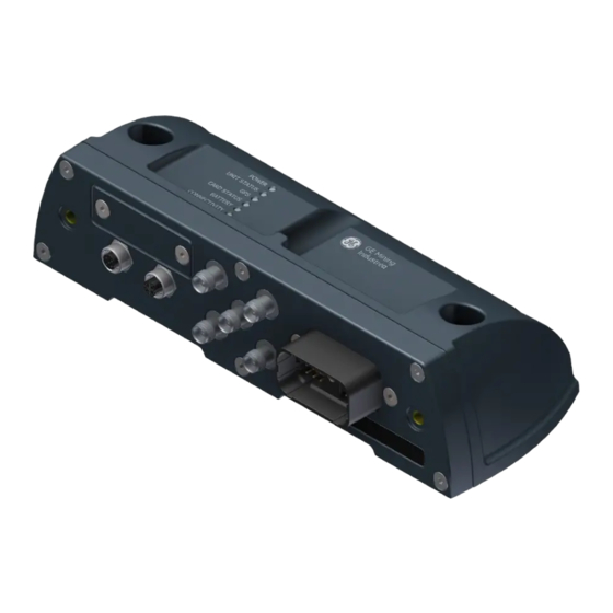
- Page 10 In-Vehicle Unit (IVU) PROD0842 PROD0847 Note: All IVUs have their “PRODXXXX” part number labelled on the flat underside of the housing. CAS-GPS IVU BASIC SYSTEMS INSTALLATION MANUAL DOCU0085 Revision Q...
- Page 11 Input Power & Signal Connections Serial number Hardware build letter code • Service SIM Card Panel USB Card Auxiliary USB External Cables Display GPS Antenna Antenna GSM Antenna, (PROD0847 only) V2V Antenna WiFi/WAN Antenna CAS-GPS IVU BASIC SYSTEMS INSTALLATION MANUAL DOCU0085 Revision Q...
- Page 12 Input Power & Signal Connections 24-Way Deutsch (Vehicle Status Electrical Connections) LEDs Power & Signal connector Display (Shown with cover in place) CAS-GPS IVU BASIC SYSTEMS INSTALLATION MANUAL DOCU0085 Revision Q...
- Page 13 IVU Mounting The IVU should be mounted such that: • The Preferred IVU mounting location is inside the cabin / electrical compartment (this will assist with future expansion) • It is in the preferred location for that vehicle type • It is easily accessible for servicing •...
- Page 14 Mounting Locations & Cable Runs The following diagrams show the preferred mounting locations and cable paths for each vehicle type. Ensure the hardware supplied in the kit is being utilised. Ensure there is a clear line of sight from all directions for the Antennas. It is a recommendation on all Haul trucks the Antennas are to protrude above the Tray by 100mm, by doing this it creates a clear line of sight for the Antennas on all vehicles.
- Page 15 Mounting Locations & Cable Runs • Follow existing cable runs where possible. • All cables to be secured using P-Clamps where possible. • Cable ties should be used as a last resort where there is no provision for P-Clamps Ensure cable ties are cut flush to avoid sharp edges.
- Page 16 Light Vehicle Note: IVU preferably mounted inside the Operator’s cabin Notes: • Antennas must be kept a minimum of 37 cm away from occupants in accordance with MPE Radiation Regulations. • Consideration must be given to EMI with the vehicle’s ECU when cable runs are being planned in accordance with local regulations and vehicle manufacturers recommendations.
- Page 17 Light Vehicle GPRS Bracket used here is Note: Antenna Spacing between V2V ATOM0033 and GPRS should be a minimum of 300mm. CAS-GPS IVU BASIC SYSTEMS INSTALLATION MANUAL DOCU0085 Revision Q...
- Page 18 Haul Truck Notes: • Antennas must be kept a minimum 37 cm away from occupants in accordance with MPE Radiation Regulations. • Consideration must be given to EMI with the vehicle’s ECU when cable runs are being planned in accordance with local regulations.
- Page 19 Haul Truck Antenna to protrude above the tray by 100mm. Ensure the antennas will clear any working obstacles. Standard fitment on opposite side of the vehicle from the operator’s cabin. Specific antennas deployed will depend on IVU type. TRAY OPERATOR’S CABIN Adjust the mast length to suit the installation.
- Page 20 Haul Truck CAS-GPS IVU BASIC SYSTEMS INSTALLATION MANUAL DOCU0085 Revision Q...
- Page 21 Haul Truck NOTE: WiFI or WHERE No WiFi OR GPRS ANTENNA IS DEPLOYED, GPRS/GSM MOUNT GPS ANTENNA AT POSITION 1 V2V ANTENNA ANTENNA SECURE NUTS WITH LOCTITE 243 GPS ANTENNA STEE0690 WASHER LOCK WASHER POSITION 2 POSITION 1 Note: An extended depth socket spanner may be required to tighten the antenna fixing nuts within the bracket channel.
- Page 22 Haul Truck Note: TOOL0264 is required to tighten the antenna coax within the bracket channel. CAS-GPS IVU BASIC SYSTEMS INSTALLATION MANUAL DOCU0085 Revision Q...
- Page 23 Haul Truck Stauff clamp sizes used must be correctly chosen for the handrail tube size from the Size 6 heavy series Stauff clamping system Available rubber inserts are: 32mm, 33.7mm, 35mm, 38.7mm, 40mm, 42mm, 45.5mm, 48mm, 51mm, 53.4mm, 56.4mm. Available clamp bodies are: 38mm, 42mm, 44.5mm, 48.3mm, 50.8mm, 55mm, 57mm, 60.3mm, 60.5mm, 65mm, 70mm.
- Page 24 Heavy vehicle (excluding Haul Truck) Note: IVU preferably mounted inside the Operator’s cabin Notes: • Antennas must be kept a minimum of 37 cm away from occupants in accordance with MPE Radiation Regulations. • Consideration must be given to EMI with the vehicle’s ECU when cable runs are being planned in accordance with local regulations and vehicle manufacturers recommendations.
- Page 25 Heavy vehicle (excluding Haul Truck) Note: An extended depth socket spanner may be required to tighten the antenna fixing nuts within the bracket channel. CAS-GPS IVU BASIC SYSTEMS INSTALLATION MANUAL DOCU0085 Revision Q...
- Page 26 Display Unit (PROD0839A) Serial number Hardware build letter code CAS-GPS IVU BASIC SYSTEMS INSTALLATION MANUAL DOCU0085 Revision Q...
- Page 27 Display Unit (PROD0839A) The client should be consulted to ensure Display Unit is mounted in a mutually agreed position. The Display Unit should be mounted such that: • It is compliant with vehicle manufacturer’s instructions, national/local and site regulations. • It does not to create any additional blind spots.
- Page 28 Display Unit (PROD0839A) Status Bar: Current status of system components Approaching Vehicle: Vehicle ID, Speed Indicator and Distance Your Vehicle: Vehicle ID and Speed Indicator Special Functions Buttons: Menu, Configuration, GPS Data, Camera selection and Data CAS-GPS IVU BASIC SYSTEMS INSTALLATION MANUAL DOCU0085 Revision Q...
- Page 29 Display Unit (PROD0839A) Screen: 7” High Brightness LCD Touch Screen with auto dimming for all lighting conditions Audio: Voice and tone output Sensors: Light sensor for automatic screen dimming LED: LED output for system status indication CAS-GPS IVU BASIC SYSTEMS INSTALLATION MANUAL DOCU0085 Revision Q...
- Page 30 Display Unit (PROD0839A) Connector: Electrical connection for power and signals RAM Mount: Multi – axis adjustable mounting bracket CAS-GPS IVU BASIC SYSTEMS INSTALLATION MANUAL DOCU0085 Revision Q...
- Page 31 CAS-CAM/RF Installations This section describes the interconnections between the CASCAM/RF system and CAS-GPS system. Refer to the CASCAM/RF installation documentation for the camera and RF installation procedure. CAS-GPS IVU BASIC SYSTEMS INSTALLATION MANUAL DOCU0085 Revision Q...
- Page 32 Upgrades If upgrading a previous CASCAM/RF installation the installed CASCAM/RF Display (PROD0119) will be removed and replaced with the CAS-GPS Display. All cables may be reused (provided they are in a serviceable condition). Some power input requirements may change depending on the requested functionality of the system.
- Page 33 Interconnections 4CAM/4RF CAS-GPS IVU BASIC SYSTEMS INSTALLATION MANUAL DOCU0085 Revision Q...
- Page 34 Interconnections – 4CAM/4RF 12 way Deutsch Expansion Unit “DISPLAY” output 24 way Deutsch connector Connections on PROD0179 – Expansion Unit inputs connector on 12 way military connector at IVU PROD0180 cable Deutsch Deutsch Wire Colour Signal/Wire CABL0114 19- Way MILSPEC Reference Colour Reference...
- Page 35 Interconnections – 1CAM/1RF PROD0850-xM CASGPS IVU TO DISPLAY CABLE CASGPS IN-VEHICLE UNIT (IVU) CASGPS DISPLAY 24 WAY DEUTSCH CONNECTOR INTERFACE HEAVY VEHICLE RF UNIT (TYPICALLY IGNITION SIGNAL PROD0169) 12 WAY DEUTSCH CONNECTOR INTERFACE PROD0181 DISPLAY UNIT INPUT 6 WAY DEUTSCH CABLE CONNECTOR INTERFACE...
- Page 36 Interconnections – 1CAM/1RF 12 way Deutsch connector 24 Way Deutsch Connector CASGPS IVU (PROD0181) PWR+ (Battery) BLACK GREY REV+ (DI3+) VIOLET REV- (DI3-) WHITE/BLACK FWD+ (DI4+) PINK/BLACK FWD- (DI4-) ORANGE BRAKE (DI2) Ignition (DI1) 6 way Deutsch connector Camera / RF Cable (PROD0182) 24 Way Deutsch Connector CASGPS IVU (PROD0182) +12V...
- Page 37 Interconnections – Light Vehicle CASGPS IN-VEHICLE UNIT (IVU) PROD0850-xM CASGPS IVU TO VEHICLE DISPLAY CABLE POWER VIA FUSE CASGPS DISPLAY LIGHT VEHICLE RF UNIT (PROD0295) REVERSE SIGNALS AND IGNITION SIGNAL 6 WAY DEUTSCH CONNECTOR INTERFACE PROD0296 LV RF INPUT CABLE CAS-GPS IVU BASIC SYSTEMS INSTALLATION MANUAL DOCU0085 Revision Q...
- Page 38 Interconnections – Light Vehicle 6 way Deutsch 24 Way Deutsch connector CASGPS 6 way Military connector RF Unit LV Power, connector (PROD0296) (PROD0296) PWR+ PWR+ BLACK BLACK BROWN BUZZER BLUE COM1 RX RS232 TX GREEN COM1 TX RS232 RX YELLOW REV+ (DI3+) REV- (DI3-) Ignition (DI1)
- Page 39 Input Power & Signal Connections – Basic CAS-GPS CAS-GPS IVU BASIC SYSTEMS INSTALLATION MANUAL DOCU0085 Revision Q...
- Page 40 Input Power & Signal Connections – Gear Decoder CAS-GPS IVU BASIC SYSTEMS INSTALLATION MANUAL DOCU0085 Revision Q...
-
Page 41: Deutsch Connector
Deutsch Connector If CAS CAM RF Deutsch Wire Heavy Vehicle IVU Function Subsystem/ Device 24 pin Colour Designation CAS-GPS Signal CAT GEAR decoder fitted COM1 RS232 txd or RS485+ SmartCap or CASCAMRF LV CAN High CAN High Self Test Node or LFM USB5V USB supply out USB +5V... - Page 42 Input Power & Signal Connections Input Power (Vin) • Vin+ should be sourced after the isolator. • WARNING: The IVU remains powered for up to 14 hours after the input power has been Isolated. • Input power / ignition pickup point must have inline short circuit protection, use supplied circuit breakers from installation kit.
- Page 43 Input Power & Signal Connections Ground Ground pickup point is the vehicle chassis. A ring terminal on a designated grounding point should be used. Ignition Signal Vehicle ignition should be protected by an independent 4 Amp fuse. Although the system does not draw operating current from this source, the vehicle’s circuit should be protected against inadvertent shorts.
- Page 44 General Wiring Principles • Blanking plugs or caps are supplied and must be in place for all unused connectors i.e. 24 way Deutsch Connector on the IVU for example • All cable joins/splices should be soldered and heat shrink insulation applied •...
- Page 45 Antenna cable terminations • You need to have received the proper training before attempting to terminate antenna cables. • Antenna cable terminations are one of the most critical components of the system. CAS-GPS IVU BASIC SYSTEMS INSTALLATION MANUAL DOCU0085 Revision Q...
- Page 46 Antenna cable terminations 1. Strip cable jacket, braid, and dielectric to dimensions in the table below for the appropriate cable and connector. All cuts are to be sharp and square. Important: Do not nick braid, dielectric, and centre conductor. Cable Type A (mm) B (mm) C (mm)
- Page 47 Antenna cable terminations 2. Slide heatshrink and outer ferrule onto cable as shown. 3. Flare slightly end of cable braid as shown to facilitate insertion of inner ferrule. Important: Do not comb out braid. Contact on Cable centre conductor Outer Ferrule Heatshrink Cable dielectric 4.
- Page 48 Antenna cable terminations 5. Install cable assembly into body assembly so that inner ferrule portion slides under braid. Push cable assembly forward until contact snaps into place in insulator. The tip of the centre contact should be level with the face of the connector. 6.
- Page 49 Antenna cable terminations 7. Move the heatshrink up over the ferrule, and shrink into place using a heat gun This will aid in preventing moisture ingress to the termination. Heatshrink here 8. Repeat steps 1-7 for the other end of the cable. CAS-GPS IVU BASIC SYSTEMS INSTALLATION MANUAL DOCU0085 Revision Q...
- Page 50 Testing Antenna cable terminations Test completed cable for continuity and short circuits by completing the following: With both ends of the cable disconnected. Measure the resistance between the inner and outer conductors. Must be open circuit (>10MΩ) >10M CAS-GPS IVU BASIC SYSTEMS INSTALLATION MANUAL DOCU0085 Revision Q...
- Page 51 Testing Antenna cable terminations Short the inner to the outer conductor on one end of the cable. Measure the resistance from the inner to the outer conductors on the opposite end. Must be low resistance (<1Ω). Shorting link If available, measure the SWR of the completed cable with a 50Ω dummy load installed in place of the antenna.
- Page 52 Antenna Cable Connection Security • Antenna cable connection points can be prone to loosening with cable movement. • Tighten antenna cable connections with adequate force to prevent loosening. • Apply self-amalgamating tape over the cable/antenna connection. This will prevent loosening and provide environmental protection •...
- Page 53 Configuration The following pages instruct on the configuration process for CAS-GPS. They are straight forward with no laptop being required. Configuration is programmed through the Graphic User Interface. (Display) Note: The Installer will need to obtain the site specific passcode from the Site Supervisor to complete the following process.
- Page 54 Configuration – Installation Measurements GPS antenna Width (from LHS) GPS Antenna Length (from front) The measurements indicated here are the dimensions of the machine and GPS Antenna location. GPS antenna location These measurements are crucial for the GPS to perform correctly and accurately.
- Page 55 Configuration – Installation Measurements Measurements shown here are an example of a Haul truck. A = Truck Length CAS-GPS IVU BASIC SYSTEMS INSTALLATION MANUAL DOCU0085 Revision Q...
- Page 56 Configuration – Installation Measurements Measurements shown here are an example of a Haul truck. C = GPS antenna height B = Truck Width CAS-GPS IVU BASIC SYSTEMS INSTALLATION MANUAL DOCU0085 Revision Q...
- Page 57 IVU Orientation • The orientation of the IVU must be recorded so that the 3 axis accelerometer can be correctly calibrated • The table (right) should be used to determine the orientation number of the installed IVU • The orientation is referenced to the vehicle if viewed from above when travelling towards the top of the page (as shown by the vehicle diagram)
- Page 58 IVU Orientation (examples) Orientation Orientation Number 1 Number 7 IVU mounted on IVU mounted the internal floor inside cabin surface behind the rear seat CAS-GPS IVU BASIC SYSTEMS INSTALLATION MANUAL DOCU0085 Revision Q...
- Page 59 Configuration Use the button at bottom of Display to access CAS-GPS CAS Installer window. Configuration Button CAS-GPS IVU BASIC SYSTEMS INSTALLATION MANUAL DOCU0085 Revision Q...
-
Page 60: Configuration Setup
This ICON will change once the Object Type has Configuration Setup been chosen Record the IVU orientation here. Enter the Asset Name (usually Click on the Orientation the vehicle’s ID) using the drop down box and select Keyboard below from the list of numbers which refer to the table The Asset type provides a record listed previously in this... -
Page 61: Network Configuration
Network Configuration The Network button shows connection status and settings Wi-Fi IP: Enter the assigned Network Addresses are by Wi-Fi IP Address for the default Dynamic until Vehicle manually assigned in the 192.168.73.189 Network Settings Page at Wi-Fi MASK: Enter the which point they will be assigned Wi-Fi MASK for the stored as static addresses. - Page 62 Shovel with Heading Overview The difficulty with rotating equipment such as shovels is that the heading cannot be determined by 1 normal GPS receiver. To overcome this a node can be installed to provide another position from which a heading can be determined. To provide the minimum error the antenna connected to the IVU and the node should be installed as far apart as possible on the machine.
- Page 63 Shovel IVU Configuration – Setup Tab Configuration should only be completed once the IVU and node are installed and have power. On the “Setup” tab the following items are A-Width significant for the IVU: • Length: The length of the body of the Shovel (not including the boom) •...
- Page 64 Shovel IVU Configuration – Self-Test Tab On the “SelfTest” tab, settings in this tab relate to the node that will provide the second GPS signal: B-Width • • Node Enable: This box must be checked CAN Bus • Comms Type: This should be set to “CAN Bus”.
-
Page 65: Node Installation
Node Installation Refer to DOCU0088 CAS-GPS SELF-TEST SUB-SYSTEM INSTALLATION MANUAL CAS-GPS IVU BASIC SYSTEMS INSTALLATION MANUAL DOCU0085 Revision Q... - Page 66 Shovel Heading Testing The second status icon indicates the communication status to the node: • Green indicates good. • Yellow indicates warning, no message received in the last 5 seconds. • Red indicates error, no message received in the last 5 minutes. Pressing the button displays the primary and secondary GPS information.
- Page 67 Shovel Heading Testing The GPS icon should always be green when a Shovel with Heading is correctly installed and operating. If the GPS icon change to yellow, this indicates that the IVU no longer has a valid heading. Potential causes: •...
- Page 68 Configuration & Install Record On completion of the physical installation: • Complete the Installation Checklist to ensure & record that the system is installed correctly and is operating as expected. • Complete the Installation Record carefully filling in all of the required details (including – orientation, GPS location, vehicle size, vehicle ID) CAS-GPS IVU BASIC SYSTEMS INSTALLATION MANUAL DOCU0085 Revision Q...
-
Page 69: Record Keeping
Record Keeping • Take photographs of the completed installation (for future reference and record of installation). • Provide all completed installation records to the Site Supervisor. CAS-GPS IVU BASIC SYSTEMS INSTALLATION MANUAL DOCU0085 Revision Q... - Page 70 Trouble Shooting - No power / Blank screen Is the vehicle’s battery Connect / charge and connected & fully charged? retest Use this diagram to troubleshoot an apparent loss or blank screen: Are all connectors plugged Connect and retest into the IVU & display? Replace &...
- Page 71 Trouble Shooting – GPS problems No fault detected by the system. If it is not Is the GPS icon Red? functioning correctly, contact an authorized representative The GPS signal status is indicated by the Does the antenna have Position vehicle to an unobstructed view have a clear view of he colour of the...
- Page 72 Trouble Shooting – V2V problems No fault detected by The Vehicle to Vehicle communication is indicated by the system. If it is not Is V2V icon Red functioning correctly, the colour of the ICON at the top of the display. contact an authorized representative Green: Communicating with other vehicles –...
-
Page 73: Service And Maintenance
Service and Maintenance Scheduled System Servicing ▪ It is recommended that the system undergo preventative scheduled maintenance and inspections. These should be carried out by trained and authorised personnel every 6 months or 1500hrs (which ever occurs first). Software Updates ▪... - Page 74 Service and Maintenance Display Unit Clean screen surface with a clean dry soft cloth – Do Not use solvents or cleaners on the screen surface Check for physical damage to screen surface Check the cable connector is securely connected at the rear of the screen – finger tighten only if loose Check the mounting bracket is secure –...
- Page 75 Decommission ▪ Removal of the system should only be performed if authorised by the owner of the vehicle. ▪ Removal should only be performed by a qualified Auto Electrician. ▪ All system components and wiring should be removed. ▪ All vehicle wiring should be restored back to original condition. ▪...
- Page 76 Disposal The electronic equipment discussed in this manual must not be treated as general waste or disposed of into landfill. By ensuring that this product is disposed of correctly, you will be helping to prevent potentially negative consequences for the environment and human health which could otherwise be caused by incorrect disposal of this product.
- Page 77 Disclaimer • The CAS product is a driver’s aid and should not be relied upon as the primary means of reducing the risks of high potential interactions between Heavy Vehicles, Light Vehicles, infrastructure and personnel. • GPS based proximity detection may not operate when satellites are not fully visible in the sky (e.g.
- Page 78 MERCHANTABILITY OR OF FITNESS FOR A PARTICULAR PURPOSE. WABTEC CORPORATION further makes no representation or warranty of accuracy of these materials and neither WABTEC CORPORATION will have no responsibility or liability for any error or omission in these materials. CAS-GPS IVU BASIC SYSTEMS INSTALLATION MANUAL...
Need help?
Do you have a question about the PROD0842 and is the answer not in the manual?
Questions and answers