
Related Manuals for PI L-812.051400B


Summary of Contents for PI L-812.051400B
- Page 1 L812UM0001EN ‒ 7/13/2022 User Manual L-812.XX1400[B|BF] LINEAR STAGE WITH STEPPER MOTOR M O T I O N | P O S I T I O N I N G...
-
Page 2: Table Of Contents
CONTENTS L812UM0001EN ‒ 7/13/2022 Contents Legal Information......................5 About this Document....................6 Objective and Target Group................6 Explanation of Symbols..................6 2.2.1 Typographic Conventions..............6 2.2.2 Symbols Used..................6 Figures........................ 7 Other Applicable Documents................7 Downloading Manuals..................8 Safety..........................9 Intended Use...................... 9 General Safety Instructions................9 Organizational Measures.................. - Page 3 CONTENTS L812UM0001EN ‒ 7/13/2022 Installation........................18 Mounting the L-812.xx1400................18 6.1.1 Mounting the L-812.xx1400 from Above........18 Connecting the L-812.xx1400 to the Protective Earth Conductor ....20 Building a Multi-Axis System................. 21 6.3.1 Building an XY Multi-Axis System..........21 Mounting the Load onto the L-812.xx1400............ 22 6.4.1 Geometric Limits for Mounting Load Masses.......
- Page 4 CONTENTS L812UM0001EN ‒ 7/13/2022 14 European Declarations of Conformity..............49 15 Appendix........................50 15.1 Pin Assignment....................50 15.1.1 Drive Connector................50 16 Glossary........................52 M O T I O N | P O S I T I O N I N G...
-
Page 5: Legal Information
With regard thereto, Physik Instrumente (PI) GmbH & Co. KG reserves all rights. The use of any text, images and drawings is permitted only in part and only when indicating the source. -
Page 6: About This Document
L-812.xx1400B, and L-812.xx1400BF (hereinafter refered to as L-812.xx1400 or L-812). Basic knowledge of closed-loop systems, motion control concepts, and applicable safety measures is assumed. Explanation of Symbols This chapter explains the symbols and markings used by PI in their user manuals. 2.2.1 Typographic Conventions Symbol / label... -
Page 7: Figures
Manual User manual for the ACS user software The latest versions of the user manuals can be downloaded (p. 8) at www.pi.ws. M O T I O N | P O S I T I O N I N G... -
Page 8: Downloading Manuals
► Contact our customer service department (p. 35). Downloading Manuals 1. Open the website www.pi.ws. 2. Search the website for the product number (e.g., L-812). 3. Click the corresponding product to open the product detail page. 4. Click the Downloads tab. -
Page 9: Safety
► Always keep this user manual available with the L-812.xx1400. The latest versions of the user manuals can be downloaded (p. 8) at www.pi.ws. ► Add all information from the manufacturer such as supplements or technical notes to the user manual. -
Page 10: General Personnel Qualification
3 SAFETY L812UM0001EN ‒ 7/13/2022 ► Only install and operate the L-812.xx1400 after you have read and understood this user manual. 3.3.2 General Personnel Qualification The L-812.xx1400 may only be installed, started up, operated, maintained, and cleaned by authorized and appropriately qualified personnel. M O T I O N | P O S I T I O N I N G... -
Page 11: Product Description
4 PRODUCT DESCRIPTION L812UM0001EN ‒ 7/13/2022 Product Description Model Overview High-load linear stage; 2-phase stepper motor; 102 to 610 mm travel range (see table); 500 N load capacity; 100 mm/s maximum velocity; ball screw L-812.xx1400B: with holding brake L-812.xx1400BF: with holding brake and folded drivetrain Product number Travel range L-812.051400[B|BF]... -
Page 12: Type Plate
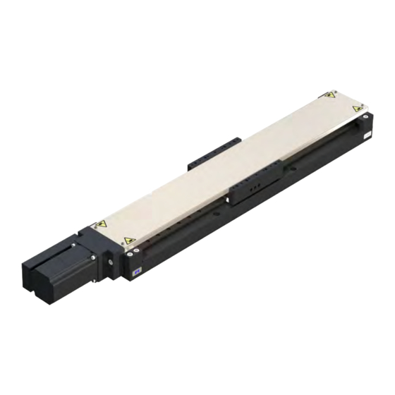
4 PRODUCT DESCRIPTION L812UM0001EN ‒ 7/13/2022 Figure 2: Product labeling on the L-812.xx1400BF 1. Warning symbol: risk of crushing 2. Connector label 3. Protective earth connector symbol 4. Type plate 5. Grease nipple labeling 4.2.1 Type Plate Figure 3: Type plate of the L-812.xx1400 1. - Page 13 4 PRODUCT DESCRIPTION L812UM0001EN ‒ 7/13/2022 Figure 4: Elements of the L-812.xx1400 and L-812.xx1400B 1. Slider with two mounting rails for the load or platform 2. Drive, on L-812.xx1400B models: with holding brake 3. Drive connector 4. Protective earth connector 5.
-
Page 14: Base Body
The protective earth connector is on the side of the L-812.xx1400's base body. The L-812.xx1400 has a lateral reference edge that can be used, for example, to align it with locating pins (see figure). The reference edge is at the bottom on the side with the PI logo (refer to "Dimensions"... -
Page 15: Direction Of Motion
4 PRODUCT DESCRIPTION L812UM0001EN ‒ 7/13/2022 Direction of Motion Figure 7: View of the L-812.xx1400's direction of motion Scope of Delivery Product number Description L-812.xx1400[B|BF] Linear stage according to the order (p. 11) L-812.05xxxx[B|BF]: L812B0014-0500 Mounting kit for mounting the L-812.xx1400, consisting of L-812.09xxxx[B|BF]: L812B0014-0900 ■... -
Page 16: Suitable Electronics
4 PRODUCT DESCRIPTION L812UM0001EN ‒ 7/13/2022 Suitable Electronics The L-812.xx1400 must be connected to suitable electronics that supply the necessary voltage for operating and if required, to evaluate the sensor and limit switch signals. The following electronics are suitable: Product number Description G-901.R319[x] ACS controller with ACS driver module, 2 / 3 / 4 axes, intermediate cir-... -
Page 17: Unpacking
5 UNPACKING L812UM0001EN ‒ 7/13/2022 Unpacking NOTICE Mechanical overload due to incorrect handling! Impermissible mechanical overload caused by lifting the L-812.xx1400 improperly could cause deformation or damage to the L-812.xx1400. ► Always use the carrying aid supplied to lift and transport the L-812.xx1400. Unpacking the L-812.xx1400 and Transporting it to its Intended Place of Use 1. -
Page 18: Installation
6 INSTALLATION L812UM0001EN ‒ 7/13/2022 Installation Mounting the L-812.xx1400 The L-812 models without holding brake may be installed horizontally only. The L-812 models with holding brake (L-812.xx1400B or L-812.xx1400BF) may also be installed vertically. WARNING Risk of injury when the L-812.xx1400B or L-812.xx1400BF is mounted vertically! The holding brake of the motor is not sufficient to ensure functional safety when operating L-812.xx1400B or L-812.xx1400BF with the motion axis aligned vertically. - Page 19 6 INSTALLATION L812UM0001EN ‒ 7/13/2022 Figure 8: Mounting the L-812.xx1400 onto an underlying surface Tools and Accessories Mounting kit for mounting the L-812.xx1400 (p. 15) ■ ■ Suitable torque wrench Requirements You have read and understood the general safety instructions (p. ✓...
-
Page 20: Connecting The L-812.Xx1400 To The Protective Earth Conductor
6 INSTALLATION L812UM0001EN ‒ 7/13/2022 b) Align the L-812.xx1400 on the underlying surface so that the corresponding mounting holes in the L-812.xx1400 and underlying surface are in line. 3. Optional: Put the L-812.xx1400 onto the underlying surface so that the locating pins are in the corresponding locating holes in the L-812.xx1400. -
Page 21: Building A Multi-Axis System
6 INSTALLATION L812UM0001EN ‒ 7/13/2022 Requirements You have read and understood the general safety instructions (p. ✓ Connecting the L-812.xx1400's Base Body to the Protective Earth Conductor 1. If necessary, attach a suitable cable lug to the protective earth conductor. 2. -
Page 22: Mounting The Load Onto The L-812.Xx1400
6 INSTALLATION L812UM0001EN ‒ 7/13/2022 Requirements You have read and understood the general safety instructions (p. ✓ The lower L-812.xx1400 is properly fixed on an underlying surface (p. 18). ✓ You have accounted for the space required to route cables according to regulations and ✓... -
Page 23: Mounting The Load Onto The L-812.Xx1400
6 INSTALLATION L812UM0001EN ‒ 7/13/2022 NOTICE Impermissibly high load on the L-812.xx1400 An impermissibly high load on the L-812.xx1400 impairs the motion and can damage the L-812.xx1400. ► Pay attention to the maximum permissible forces (p. 36) that may act on the L-812.xx1400. -
Page 24: Mounting The Motion Platform Onto The L-812.Xx1400
6 INSTALLATION L812UM0001EN ‒ 7/13/2022 You have prepared the load so that it can be fixed to the mounting holes in the mounting ✓ rails of the L-812.xx1400. Mounting the Load onto the L-812.xx1400 1. Optional: Insert the locating pins into the respective holes in the mounting rails of the L-812.xx1400. -
Page 25: Mounting The Load Onto An Installed Motion Platform
► Make sure that the electronics support the drive type of the L-812.xx1400 and have been configured accordingly. ► Use cables from PI miCos only to connect the L-812.xx1400 to the electronics. ► Pay attention to correct pin assignment (p. - Page 26 6 INSTALLATION L812UM0001EN ‒ 7/13/2022 Tools and Accessories Suitable electronics (p. 16) ■ ■ Drive cable, suitable for the electronics ■ If necessary: Suitable screwdriver for the locking screws of the connectors. Requirements You have read and understood the general safety instructions (p. ✓...
-
Page 27: Startup And Operation
7 STARTUP AND OPERATION L812UM0001EN ‒ 7/13/2022 Startup and Operation Starting and Operating the L-812.xx1400 Requirements You have read and understood the general safety instructions (p. ✓ You have installed (p. 18) the L-812.xx1400 correctly. ✓ Sie haben die Tragehilfe entfernt (p. 17). - Page 28 7 STARTUP AND OPERATION L812UM0001EN ‒ 7/13/2022 NOTICE Operating voltage excessively high or incorrectly connected! Operating voltages that are too high or incorrectly connected can cause damage to the L-812.xx1400. ► Pay attention to the operating voltage range (p. 44), which is specified for the L-812.xx1400.
-
Page 29: Maintenance
8 MAINTENANCE L812UM0001EN ‒ 7/13/2022 Maintenance CAUTION Burning due to hot surface! The drive of the L-812.xx1400 and the surroundings can heat up during operation. Touching the L-812.xx1400 and surrounding parts can result in minor injuries from burning. ► If touching the motor surface cannot be excluded during maintenance, perform any maintenance work at the earliest one hour after switching off the L-812.xx1400. -
Page 30: Retensioning The Toothed Belt
8 MAINTENANCE L812UM0001EN ‒ 7/13/2022 Overview Figure 14: Position of the L-812's grease nipple Lubricating the L-812.xx1400 1. Remove the threaded pin from the nipple of the L-812.xx1400. 2. Attach an M6 lubrication connector to the nipple to apply the lubricant. 3. -
Page 31: Cleaning
8 MAINTENANCE L812UM0001EN ‒ 7/13/2022 ■ Hex key AF 2.5 ■ Frequency meter Requirements You have disconnected the L-812.xx1400 from the electronics. ✓ Retensioning the Positioner's Toothed Belt 1. Loosen the four M3 screws on the front of the positioner and remove the cover plate. 2. -
Page 32: Manually Moving The Mounted Load
8 MAINTENANCE L812UM0001EN ‒ 7/13/2022 Manually Moving the Mounted Load It might be necessary to move the mounted load manually ■ to give access to the mounting holes in the positioner's base body for the mounting screws, ■ to move the mounted load away from the hard stop and so re-establish operational readiness of the L-812.xx1400. -
Page 33: Troubleshooting
Defective electronics ► Check the electronics. Limit switches were triggered ► If you are using a controller from PI: Switch on the servo mode for the affected axis again in the PC software. ► Command the axis to move away from the limit switch. -
Page 34: Transportation
10 TRANSPORTATION L812UM0001EN ‒ 7/13/2022 Transportation NOTICE Mechanical overload due to incorrect handling! Impermissible mechanical overload caused by lifting the L-812.xx1400 improperly could cause deformation or damage to the L-812.xx1400. ► Always use the carrying aid supplied to lift and transport the L-812.xx1400. Preparing the L-812.xx1400 for Transporting 1. -
Page 35: Customer Service Department
L812UM0001EN ‒ 7/13/2022 Customer Service Department For enquiries and orders, contact your PI miCos representative or send us an email. If you have any questions concerning your system, provide the following information: ■ Product and serial numbers of all products in the system ■... -
Page 36: Technical Data
12 TECHNICAL DATA L812UM0001EN ‒ 7/13/2022 Technical Data Subject to change. You can find the latest product specifications on the product web page at www.pi.ws. 12.1 Specifications 12.1.1 L-812.051400BF Motion L-812.051400[B|BF] Tolerance Active axes Travel range in X 102 mm Acceleration in X, unloa- 10 m/s²... - Page 37 377 N Typ. rection of motion in X Resistance phase-phase 0.5 Ω Typ. Inductance phase-phase 1.2 mH Mechanical properties L-812.051400 L-812.051400B / Tolerance L-812.051400BF Guide Recirculating ball bear- Recirculating ball bear- ing guide ing guide Drive screw type Ball screw...
-
Page 38: L-812.091400[B|Bf]
12 TECHNICAL DATA L812UM0001EN ‒ 7/13/2022 Miscellaneous L-812.051400[B|BF] Tolerance Connector HD D-sub 26-pin (m) Recommended control- Ready for immediate use with fully integrated con- lers / drivers troller of the G-910 and G-901.R319 series. Flexible integration with compact modules: ACS SPiiPlusEC and UDMpa. - Page 39 12 TECHNICAL DATA L812UM0001EN ‒ 7/13/2022 Drive properties L-812.091400[B|BF] Tolerance Drive type 2-phase stepper motor Motor resolution 200 Full steps/rev. Nominal voltage 48 V Nominal current, RMS 4.2 a Typ. Peak current, RMS 4.2 a Typ. Drive force in negative di- 377 N Typ.
-
Page 40: L-812.171400[B|Bf]
12 TECHNICAL DATA L812UM0001EN ‒ 7/13/2022 Miscellaneous L-812.091400[B|BF] Tolerance Connector HD D-sub 26-pin (m) Recommended control- Ready for immediate use with fully integrated con- lers / drivers troller of the G-910 and G-901.R319 series. Flexible integration with compact modules: ACS SPiiPlusEC and UDMpa. - Page 41 12 TECHNICAL DATA L812UM0001EN ‒ 7/13/2022 Drive properties L-812.171400[B|BF] Tolerance Drive type 2-phase stepper motor Motor resolution 200 Full steps/rev. Nominal voltage 48 V Nominal current, RMS 4.2 a Typ. Peak current, RMS 4.2 a Typ. Drive force in negative di- 377 N Typ.
-
Page 42: L-812.251400[B|Bf]
12 TECHNICAL DATA L812UM0001EN ‒ 7/13/2022 Miscellaneous L-812.171400[B|BF] Tolerance Connector HD D-sub 26-pin (m) Recommended control- Ready for immediate use with fully integrated con- lers / drivers troller of the G-910 and G-901.R319 series. Flexible integration with compact modules: ACS SPiiPlusEC and UDMpa. - Page 43 12 TECHNICAL DATA L812UM0001EN ‒ 7/13/2022 Drive properties L-812.251400[B|BF] Tolerance Drive type 2-phase stepper motor Motor resolution 200 Full steps/rev. Nominal voltage 48 V Nominal current, RMS 4.2 a Typ. Peak current, RMS 4.2 a Typ. Drive force in negative di- 377 N Typ.
-
Page 44: 12.1.5 Limit Switch Specifications
12 TECHNICAL DATA L812UM0001EN ‒ 7/13/2022 Miscellaneous L-812.251400[B|BF] Tolerance Connector HD D-sub 26-pin (m) Recommended control- Ready for immediate use with fully integrated con- lers / drivers troller of the G-910 and G-901.R319 series. Flexible integration with compact modules: ACS SPiiPlusEC and UDMpa. -
Page 45: Dimensions
12 TECHNICAL DATA L812UM0001EN ‒ 7/13/2022 Area of application For indoor use only Maximum altitude 2000 m above msl Relative humidity Max. 80 %, not condensing Storage temperature 0 °C to 40 °C Transport temperature 0 °C to 40 °C Overvoltage category according to EN 60664-1 / VDE 0110-1 Supply voltage fluctuations... -
Page 46: 12.4.1 L-812.Tt1 Motion Platform
12 TECHNICAL DATA L812UM0001EN ‒ 7/13/2022 12.4.1 L-812.TT1 Motion Platform Figure 17: Dimensions of the L-812.TT1 platform, available as optional accessory Dimensions in mm. Note that a comma is used in the drawings instead of a decimal point. 12.5 Drive Properties For adjustment of the drive electronics to the L-812.xx1400, the following parameters may be necessary. - Page 47 12 TECHNICAL DATA L812UM0001EN ‒ 7/13/2022 Figure 18: Linearity deviation from the reference edge Line of motion // Reference edge < 30 µm The parallelism error between the linear guide of the L-812.xx1400 and the reference edge is < 30 µm. M O T I O N | P O S I T I O N I N G...
-
Page 48: Old Equipment Disposal
In order to fulfil the responsibility as the product manufacturer, PI miCos undertakes environmentally correct disposal of all PI miCos equipment free of charge, if it was made available to the market after August 13, 2005. Any old PI miCos equipment can be sent free of charge to the following address:... -
Page 49: European Declarations Of Conformity
14 EUROPEAN DECLARATIONS OF CONFORMITY L812UM0001EN ‒ 7/13/2022 European Declarations of Conformity Declarations for installing an incomplete machine as defined by the Machinery Directive have been issued for the L-812.xx1400. The incomplete machine still complies with all provisions in the EMC directive as well as the RoHS directive. -
Page 50: Appendix
15 APPENDIX L812UM0001EN ‒ 7/13/2022 Appendix 15.1 Pin Assignment 15.1.1 Drive Connector Figure 19: D-sub HD 26 (m) Function Input: Motor voltage, phase A, + Input: Motor voltage, phase A, + Input: Motor voltage, phase A, - Input: Motor voltage, phase A, - Input: Motor voltage, phase B, + Input: Motor voltage, phase B, + Input: Motor voltage, phase B, -... - Page 51 15 APPENDIX L812UM0001EN ‒ 7/13/2022 Function Not connected Not connected Not connected Ground Not connected M O T I O N | P O S I T I O N I N G...
-
Page 52: Glossary
Each limit switch sends its signal to the controller on a dedicated line. The controller then interrupts the motion avoiding that the positioner moves until the hard stop and gets damaged. PI positioners have mechanical, noncontact optical or Hall effect limit switches. Load Capacity Maximum load in the vertical direction when the L-812.xx1400 is mounted horizontally. - Page 53 L812UM0001EN ‒ 7/13/2022 Specifications The performance specifications are checked before dispatch. The performance specifications apply to room temperature (22 ±3 °C), systems in closed-loop operation are calibrated at this temperature. It may be necessary to reset the operating parameters when operating at considerably lower or higher temperatures.
Need help?
Do you have a question about the L-812.051400B and is the answer not in the manual?
Questions and answers