Table of Contents
Advertisement
Quick Links
Advertisement
Table of Contents

Related Manuals for De Haardt XTRA.BLACK BOX


Summary of Contents for De Haardt XTRA.BLACK BOX
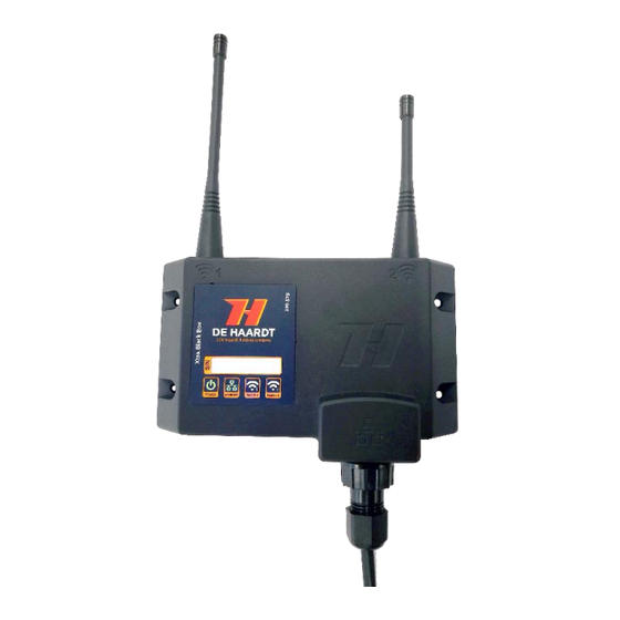
- Page 1 XTRA.BLACK BOX User manual 200.520 Document version: Datum: 21-1-2021...
-
Page 2: Copyright
The symbols in the red bordered boxes (these ones: ) are designed by Freepik. Copyright 2021 De Haardt bv Marithaime 6 6662 WD Elst (Gld) The Netherlands Tel.: +31 481 353 202 Email: support@de-haardt.com... -
Page 3: Table Of Contents
Xtra.Black Box Table of Contents ..................................2 OPYRIGHT ..................................2 AFETY GET STARTED ..............................4 ’ ............................4 S IN THE BOX ..............................6 NSTALLATION 1.2.1 ............................7 ANGE XTENDER 1.2.2 ............................8 CCESS OINT 1.2.3 ............................. 8 IMING 1.2.4 ............................. -
Page 4: Get Started
Xtra.Black Box 1 Get started This manual helps with correctly installing, configuring and using the Xtra.Black Box. Every functionality the Xtra.Black Box offers will be explained. What’s in the box Before proceeding, check the contents of the kit. The box consists of the following parts: Xtra.Black Box... - Page 5 Xtra.Black Box Power over Ethernet (PoE) injector 5 meter Ethernet cable (with one waterproof connector) Ferrite block attached on the ethernet cable. v 1.3...
-
Page 6: Installation
Xtra.Black Box Installation The Xtra.Black Box communicates wireless with the transponders in the kart. For an optimal wireless coverage the location is very important and must be chosen carefully! Placement depends on functionality. The Xtra.Black Box can be used as: •... -
Page 7: Range Extender
1.2.1 Range Extender On big kart tracks the karts can be outrange of the Xtra.Remote Control. To extend the range of the De Haardt wireless system the Xtra.Black Box can be used. This functionality can operate without ethernet communication. To provide power to the Xtra.Black Box the ethernet cable with the delivered Power over Ethernet (PoE) must be used. -
Page 8: Access Point
Placement depends on the type of use. Contact support@de-haardt.com or your software supplier. 1.2.3 Timing Host The Xtra.Black Box is capable of timing and can be switched to timing mode through the web interface. See Chapter 3 how to access the web interface. v 1.3... - Page 9 Figure 3: transmit example of the lap time to the Xtra.Timing Host The example given in figure 4 consists of the coverage of an Xtra.Black Box if it is placed at location A (left-sided of the finish line) and if that one is placed at location B (right-sided of the finish line).
- Page 10 Xtra.Black Box Figure 4: placement of the Xtra.Black Box relative to the Xtra.Beacon (marked as finish) For intermediate lap times multiple Xtra.Beacons can be used. Every Xtra.Beacon require their own Xtra Black Box in timing mode, see figure 6. Figure 5 Intermediate lab times...
-
Page 11: Mounting
Xtra.Black Box 1.2.4 Mounting The Xtra.Black Box can be mount with four M4 screws, see figure 6. Figure 6 Xtra.Black Box mounting Antennas must be vertical and pointed upward, see figure 7. Figure 7 Vertical mounting v 1.3... -
Page 12: Ethernet
Xtra.Black Box Mounting the Xtra.Black Box on a wall can reduce the strength of the radio. In particular walls or fences with steel in it, see figure 8. Figure 8 Range and obstacles 1.2.5 Ethernet The Xtra.Black Box can be connected with ethernet to provide power and data communication. The delivered ethernet cable has a waterproof connector on one side, see figure 9. - Page 13 Xtra.Black Box Figure 9 Waterproof ethernet connector WARNING! One side of the cable is NOT waterproof. Be sure it is protected against water! v 1.3...
-
Page 14: Antennas
Figure 10 Front with led indication 2.1.2 LED indicator 2.1.2.1 Power The first led is the power led this shows if the Xtra.Black Box is powered or not. LED Color Description Green Xtra. Black Box is powered. The device is ON Xtra. -
Page 15: Software Interface/ Advanced Manual
Radio 2 The fourth led displays the radio 2 communication. LED Color Description White Radio2 is active: send or received De Haardt Dual band messages No De Haardt dual band activity 2.1.3 Software interface/ advanced manual Please contact support@de-haardt.com for the advanced manual. -
Page 16: Configurations
3 Configurations Is the Xtra.Black Box is connected with ethernet to a local network or internet. It’s settings can be changed with a computer. To connect with the Xtra.Black Box see 3.1 Find and Connect on network. If there is connection, the setting can be changed using the Xtra.Black Box’s webpage, see 3.2 Find and Connect on network. -
Page 17: Home
Xtra.Black Box 3.2.1 Home The home screen shows all the currently set information such as the mode, IP address and enabled tracks. Figure 12 Webpage Home 3.2.2 Setup The setup screen is where all the settings can be changed. The setup page has been divided into 5 sections. Each section will be further explained. - Page 18 Under the LAN section two options can be selected. Dynamic IP(default) and Static IP. When the LAN mode has been changed the Xtra.Black Box needs to be restarted for it to take effect. Remove the Xtra.Black Box power or use the reset button.
- Page 19 Using the dropdown box the Xtra.Black Box can switch between access point mode and timing mode. Access point is the default mode which enables the Xtra.Black Box to act as a range extender. Timing mode sets the Xtra.Black Box to listen to timing messages. The tracks can be enabled and disabled using the check boxes. By default all the tracks are enabled.
- Page 20 The second feature sets the Xtra.Black Box to master or slave mode to sync the CAN data messages. This feature requires two Xtra.Black Box one set to master mode and one set to slave mode. The sync IP address of the master has to be set to the IP address of the slave.
- Page 21 Xtra.Black Box The scan is ready when the white LED (RADIO2) stops flashing simultaneously. Press “show kart list” to show the active kart. Figure 18 Webpage CAN kart list, kart nr 42 is active v 1.3...
-
Page 22: System Tools
Xtra.Black Box 3.2.3 System Tools The system tools page is where the firmware can be uploaded from the PC into the Xtra.Black Box. Figure 19 System tools 3.2.3.1 Update server There are two options to upgrade to a new firmware. Online update and manual update is possible. The online update is described in this paragraph, for manual update see 3.2.3.2. - Page 23 3.2.3.2 Web Firmware upgrade (Manual firmware update) When there is a new firmware available it can be uploaded through the PC to the Xtra.Black Box. To do this press browse file and select the firmware file. Figure 21 Webpage firmware upgrade Figure 22 Firmware upgrade select file Select the File that we send to you.
-
Page 24: Telnet Connection
Wait till the download is complete or the blackbox will not be updated. Telnet connection Set up a Telnet communication between the PC and Xtra.Black Box. Make sure they are both connected to the same network. Follow these steps if you do not know how to set up the connection. -
Page 25: Technical Specification
[1] Environment has a big influence Water and dust resistance The Xtra.Black Box is rated as an IP65 device. Only when the Xtra.Black Box antennas and waterproof* ethernet connector is used. *see chapter 1.2.5 Ethernet Power over Ethernet The Xtra.Black Box is in compliance with IEEE 802.3af. -
Page 26: Support
Xtra.Black Box 5 Support For support, one can contact De Haardt’s support department by email: support@de-haardt.com. v 1.3...
Need help?
Do you have a question about the XTRA.BLACK BOX and is the answer not in the manual?
Questions and answers