Table of Contents
Advertisement
Advertisement
Table of Contents

Related Manuals for De Haardt Xtra. Series


Summary of Contents for De Haardt Xtra. Series
- Page 2 Any trademarks, trade names, service marks or service names owned or registered by any other company and used in this manual are property of their respective companies. All rights reserved. De Haardt Electronic Engineering BV Nijverheidsweg 19-b 6662 NG Elst (GLD) The Netherlands Tel: 0481 353202...
-
Page 3: Table Of Contents
Manual Xtra.Remote Kart & Track Control System Index Index ..............2 Safety summary ............ 4 Introduction ............5 Installation ............6 Xtra.Remote Control Unit ......... 6 4.1.1 Placing the batteries ......... 6 4.1.2 Connecting the adapter ......8 4.1.3 Connecting the antenna ......8 4.1.4 Connecting to a Personal Computer .... - Page 4 Manual Xtra.Remote Kart & Track Control System 5.1.5 Adjust the speed of all karts at once ..33 5.1.6 Adjusting the speed in multiple sectors ..33 5.1.7 Penalties ..........34 5.1.8 Adjusting the speed in steps .....34 5.1.9 Repeating last command ......35 5.1.10 Operating (race) lights ......35 Menu functions ..........35...
-
Page 5: Safety Summary
Manual Xtra.Remote Kart & Track Control System Safety summary To ensure thorough understanding of all functions and to ensure efficient use of the system, please read this manual carefully before using. Please observe the following basics to prevent fire, burn, electric shock, and personal injury: •... -
Page 6: Introduction
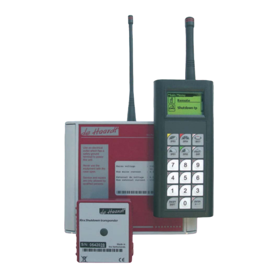
Manual Xtra.Remote Kart & Track Control System Introduction This document describes the standard operation and installation of the Xtra.Remote Kart and track control system. The different parts of a standard Xta.Remote Kart and Track Control system are : • Xtra.Remote Control Unit •... -
Page 7: Installation
Manual Xtra.Remote Kart & Track Control System Installation Xtra.Remote Control Unit The following accessories are related to Remote Control Unit: • Remote Control Unit • Adapter • Serial cable • Pair of rechargeable batteries • Carriage bag 4.1.1 Placing the batteries The Xtra.Remote Control Unit can be equipped with 2 rechargeable NiMH batteries type AA. - Page 8 Manual Xtra.Remote Kart & Track Control System 1. Open battery cover 2. ‘Unlock’ the spring 3. Place the batteries in the battery compartment 4. close the spring 5. Close the cover The provided rechargeable batteries must be charged before use.
-
Page 9: Connecting The Adapter
Manual Xtra.Remote Kart & Track Control System 4.1.2 Connecting the adapter Connect the provided adapter to the DC power connector of the Xtra.Remote Control unit and plug the adapter into the mains power supply socket. By connecting the adapter to the Remote Control it can be used without batteries and/or charge the NiMH batteries in the Xtra.Remote Control. -
Page 10: Connecting To A Personal Computer
Manual Xtra.Remote Kart & Track Control System 4.1.4 Connecting to a Personal Computer The Xtra.Remote Control can be connected to a PC by means of a serial cable. This serial link gives third parties the ability to control and monitor the karts and track by means of a PC. Xtra.Shutdown transponder To be able to limit the speed of the karts from a distance, the Xtra.shutdown transponders have to be assembled on... -
Page 11: 4.2.1 Assembly Of The Xtra.shutdown Transponder
Manual Xtra.Remote Kart & Track Control System is also assigned to the same track will have control over this kart number. The Xtra.Shutdown transponder is standard provided with a connection for a brake switch. If a brake switch is connected and activated by pressing the brake pedal of the go-kart, the RPM of the kart is reduced. - Page 12 Manual Xtra.Remote Kart & Track Control System Place each of the double sided adhesive strips on one of the slanting V sides on the bottom part of the Xtra.shutdown transponder. Next, place the Xtra.Shutdown transponder on for example a frame tube of the kart, so that the adhesive strips keep the Xtra.Shutdown transponder in place.
- Page 13 Manual Xtra.Remote Kart & Track Control System the transponder is still properly fastened and shows no visual damage. Keep the upper part (Flat part) of the Xtra.Shutdown transponder away from any metal parts or wires and never place it facedown towards the track concrete. There is no kart number printed on the Xtra.Shutdown transponder, only a serial number.
-
Page 14: Electrical Connection Of The Xtra.shutdown Transponder
Manual Xtra.Remote Kart & Track Control System 4.2.2 Electrical connection of the Xtra.Shutdown transponder Depending on the type of Xtra.Shutdown transponder you use, one or 2 cables are coming out of the Shutdown transponder. The second cable on an Xtra.Twin Shutdown transponder is connected in a simular fashion as the cable for the first engine, and therefore not specifically described in the text below. - Page 15 ! Be sure that the protection cap is fully covering all outside metal parts of the network port connector. It’s not allowed to connect any device which is not approved by De Haardt to this network port.
-
Page 16: Xtra.range Extender / Accesspoint
Manual Xtra.Remote Kart & Track Control System Xtra.Range Extender / Accesspoint The Xtra.Range Extender / Accesspoint has a “relay”or “repeater” approach which helps to cover large areas, reflective corners and hard-to-reach areas on the race circuit. The unit can also be used as an access point in case it is connected to the serial port of an external device. - Page 17 Manual Xtra.Remote Kart & Track Control System For indoor use the Xtra.Range extender / Accesspoint can be mounted for example on a fixure which is located on a building wall or on a pole. The fixture must provide a distance of at least 35cm between the Xtra.RangeExtender- Accesspoint and the wall.
- Page 18 Manual Xtra.Remote Kart & Track Control System A rubber sheet of around 5mm thickness can be used to prevent the baseplate from bending in case of tight tolerances between the tube diameter and bridge support. Fasten the Xtra.Range extender / Access point on a baseplate with 4 screws (6mm diameter) and self locking nuts.
-
Page 19: Electrical Connections Of The Xtra.range Extender / Accesspoint
Manual Xtra.Remote Kart & Track Control System 4.3.2 Electrical connections of the Xtra.Range Extender / Accesspoint The Xtra.Range extender can be powered by: • 230 Vac mains power supply • 12 Volt dc supply, like a battery, solar panel or external dc supply. - Page 20 Manual Xtra.Remote Kart & Track Control System 6. Loosen the gland and the power cord cable can be removed from the Xtra.Range extender / Accesspoint. Once the power cord is removed, the 12 Volt supply cable can be inserted through the gland.
- Page 21 Manual Xtra.Remote Kart & Track Control System...
-
Page 22: Xtra.(Warning) Light Control Board
Manual Xtra.Remote Kart & Track Control System Xtra.(warning) light control board The Xtra.Range extender/Accesspoint can be extended with a light control board. By way of this board three 230V switched outputs are created which for example can be used to turn on and off start, stop and (sector) warning lights. In addition the light control has 4 low voltage inputs (12 Volt), which can be used to externally control the lights. -
Page 23: Wiring The Light Control Board
Manual Xtra.Remote Kart & Track Control System When positioning the light control board on the Xtra.Range extender board, be sure that the pin header on the Range extender board is on the same position as the connector on the backside of the light control board. - Page 24 Manual Xtra.Remote Kart & Track Control System power connector has dual locking lances. Be sure these are latched when the board is installed.
- Page 25 Manual Xtra.Remote Kart & Track Control System Wire color Explaination Blue Neutral Brown Live ( Phase ) Black Switched Live (Phase) Yellow-Green Earth The light control board is separately fused (6,3A/Slow). For the 3 switched output channels there are individual connectors available on the light control board, as illustrated above.
- Page 26 Manual Xtra.Remote Kart & Track Control System Given above is an example wiring for the 4 external control input signals. The table below describes the functions of the 8 pins of the external input connector. External Description input pin (-) input 1 pin (+) input 1 pin (-) input 2 pin (+) input 2 pin...
-
Page 27: Xtra.sector Control System
Manual Xtra.Remote Kart & Track Control System (-) input 4 pin (+) input 4 pin Both external 12Vdc and 12Vac ( 50 / 60 Hz ) input signals can be used for the input. Use a multicore (Control) cable to connect the external inputs to the controlling device. - Page 28 Manual Xtra.Remote Kart & Track Control System automatically reduced while the other karts on the track retain their normal speed. When a kart exits the pits, the speed is set to normal. For circuits having 2 (or more) tracks which can be combined into one big track, the system can change the Track/Group settings of the Xtra.Shutdown transponder by simply driving a kart through the ‘configuration sector’.
-
Page 29: Electrical Connection Of The Xtra.sector Beacon
Manual Xtra.Remote Kart & Track Control System The Xtra.Sector Beacon can be configured for both driving directions, in case a separate “Driving Direction Unit” is used. As this unit is NOT supplied normally with the Xtra.Sector Beacon, this function is not further explained. 4.5.1 Electrical connection of the Xtra.Sector Beacon The LOOP wire is placed in a... -
Page 30: Mounting Of The Xtra.sector Sensor
Manual Xtra.Remote Kart & Track Control System them to the required length and place the crimp sleeves. Once the soldering is finished position the crimp sleeves over the solder connections and crimp the sleeves with a heat gun. The power for Xtra.Secor Beacon is provided by... -
Page 31: Electrical Connection Xtra.sector Sensor
Manual Xtra.Remote Kart & Track Control System Every go-kart requires its own Xtra.Sector Sensor. It is essential that the Xtra.Sector Sensor is installed according to the descriptions below, otherwise performance problems or even damage can be expected. The most important rules of installation are: •... - Page 32 Manual Xtra.Remote Kart & Track Control System The network port is protected with a rubber cap normally. This rubber cap has to be removed before the network connector can be attached. Check the polarisation before fitting the connector ! Once attached double check the coupled connectors and make 100% sure that vibration can not loosen the connection.
-
Page 33: Operating The Equipment
Manual Xtra.Remote Kart & Track Control System Operating the equipment Basic operation of the Xtra.Remote Control 5.1.1 Switching the Remote Control On/Off Press the ON/OFF button on the keyboard of the Xtra.Remote control for at least one second to turn the device on. -
Page 34: Adjusting The Speed Of A Group Of Karts
Manual Xtra.Remote Kart & Track Control System 5.1.4 Adjusting the speed of a group of karts Before this function can be used, the user has to assign (one time only) group(s) number(s) to the Xtra.shutdown transponder. This can be done by means of "Menu- >Shutdown tp->Assign”. -
Page 35: Penalties
Manual Xtra.Remote Kart & Track Control System Also it is possible to adjust the speed of a certain group of karts in one or more sectors. In this case enter the group number followed by the GRP button before the SPD button is pressed. -
Page 36: Repeating Last Command
Manual Xtra.Remote Kart & Track Control System 5.1.9 Repeating last command To repeat the last speed command, press de upper right button ( SECT ) 5.1.10 Operating (race) lights Default the Xtra.Remote control can operate the Red, Yellow and Green (race) lights. To operate the Red lights press SHIFT SPD4 To operate the Yellow lights press... -
Page 37: Menu->Remote->Track
Manual Xtra.Remote Kart & Track Control System 5.2.1 Menu->Remote->Track By means of this menu the circuits (TRACKs) can be turned On or Off to which this remote control is part of. The circuits are indicated with the characters A, B, C and D. With the UP and DOWN buttons you can scroll through the menu and with the ENTER button the circuit can be turned On or Off. -
Page 38: Menu->Remote->Penalty Time
Manual Xtra.Remote Kart & Track Control System 5.2.5 Menu->Remote->Penalty Time One of the 4 displayed penalty times can be chosen in this menu. With the UP and DOWN button you can scroll thru the menu and with the ENTER button one of the penalty times can be selected. -
Page 39: Menu->Shutdown Tp->Read Timer
Manual Xtra.Remote Kart & Track Control System Scroll to the [NEXT] item and press the ENTER button, to upload the settings to the Xtra.shutdown transponder. 5.2.8 Menu->Shutdown tp->Read timer By entering the kart or serial number of the Xtra.Shutdown transponder you can read out the running time of that kart. 5.2.9 Menu->Shutdown tp->Reset timer By entering the kart number or the serial number of the Xtra.Shutdown transponder the running time counter can be... -
Page 40: Menu->Rangeextend->Track
Manual Xtra.Remote Kart & Track Control System 2. The brake switch RPM limit is configured by pressing the numerical buttons. If you want to delete a number press SPD3 The brake switch RPM limit ranges from 1600 to 6500 RPM Important : Due to the nature of limiting the speed by way of spark suppression, fluctuations in speed can occur once the speed... -
Page 41: Configuration Of The Xtra.sector Beacon
Manual Xtra.Remote Kart & Track Control System Configuration of the Xtra.Sector Beacon The Xtra.Sector Beacon can be configured by using the ‘magnetic tip pen’ on the front panel of the unit. Number Explanation The DOT indicates that the internal MODE switch is activated by the ‘magnetic tip pen’. -
Page 42: Mode -> Sector Number
Manual Xtra.Remote Kart & Track Control System The DOT indicates that the internal SETTING switch is activated by the ‘magnetic tip pen’. Same as number 3. Every time the ‘magnetic tip pen’ is held near the MODE cross (2), the next mode is shown on the left part of the display. -
Page 43: Mode -> Function Number
Manual Xtra.Remote Kart & Track Control System In case sector number 0 is selected, the Xtra.Sector beacon is put in standbye mode. The result is that the Xtra.Sector sensor will ignore all Xtra.Sector beacon commands. Only the Led indicator on top of the Xtra.Sector sensor flashes for diagnostic purposes. -
Page 44: Mode -> Address
Manual Xtra.Remote Kart & Track Control System Group number 3. Configure Xtra.Shutdown transponder for Group number 4. Configure Xtra.Shutdown transponder for Group number 5. Configure Xtra.Shutdown transponder for Track Configure Xtra.Shutdown transponder for Track Configure Xtra.Shutdown transponder for Track Configure Xtra.Shutdown transponder for Track Function numbers not mentioned above are reserved for future purposes. - Page 45 Manual Xtra.Remote Kart & Track Control System Number of Diagnostic result flashes Bad reception or faulty data received Reception acceptable Reception good...
-
Page 46: Weee Legislation
Manual Xtra.Remote Kart & Track Control System WEEE Legislation European Directive 2002/96/EC requires that the equipment bearing this symbol on the product and/or its packaging must not be disposed of with unsorted municipal waste. The symbol indicates that this product should be disposed of separately from regular household waste streams. -
Page 47: Declaration Of Conformity
Manual Xtra.Remote Kart & Track Control System Declaration of Conformity We, the undersigned, Company De Haardt Electronic Engineering BV Address Nijverheidsweg 19-b 6662 NG, Elst (GLD) Country The Netherlands declare that the following equipment : Xtra.Shutdown Transponder Xtra.Twin Shutdown Transponder Xtra.Remote Control... -
Page 48: Technical Specifications
Manual Xtra.Remote Kart & Track Control System Technical specifications Xtra.Remote Control Dimensions LxBxH = 172x77x25 mm (without antenna) Maximum number of karts 1.000.000, 245 custom assignable (short) kart numbers Keyboard Membrane with tactile feedback Display Graphic LCD, with backlight Radio technology 2 way communication Battery standby time 96 hours... - Page 49 Manual Xtra.Remote Kart & Track Control System Chargetime 16 hours Buzzer Integrated Power supply • Mains adapter • Batteries Batteries 2 x High capacity Rechargeble Ni-MH, size AA, min 2100 mAh Battery charger Integrated PC. connection RS-232 port Humidity Max 85% relative Traffic , Racelight Control Default Speed 1 limit 2100 RPM...
-
Page 50: Xtra.shutdown Transponder
Manual Xtra.Remote Kart & Track Control System Xtra.Shutdown transponder Dimensions LxBxH = 76x67x39.5 mm Antenna Integrated Maximum number of karts Approx. 1.000.000 245 custom assignable (short) kart numbers Maximum number of groups 5 custom assignable group numbers Maximum number of tracks 4 custom selectable Engine shutdown Operating principle... -
Page 51: Xtra.range Extender / Access Point
Manual Xtra.Remote Kart & Track Control System Motor type Honda GX160/GX200 and compatible Engine running time counter Real time readable with the Xtra.remote control. Kart type Single engine & twin engine versions available Enclosure Mountable on round and square tubes, supported with tie-wrap feeds. -
Page 52: Light Control Board
Manual Xtra.Remote Kart & Track Control System 0.1 Amps, whithout light control board installed. Maximum current external dc 250 mA. port. Software upgradable Weight Approx 1650 grams Light control board Outputs 3 channels ( Mains switches ) Output light patterns •... -
Page 53: Xtra.sector Beacon
Manual Xtra.Remote Kart & Track Control System Xtra.Sector Beacon Dimensions LxWxT = 116 x 91 x 81 mm Display type Functions User selectable : • Sector Speed control • Limit SPEED to 2100 • Limit SPEED to 3000 • Limit SPEED to 4000 •... -
Page 54: Xtra.sector Sensor
Manual Xtra.Remote Kart & Track Control System Weight adapter Approx. 875 grams Temperature range -10 … +55 Degrees Celsius Xtra.Sector Sensor Dimensions LxWxT = 67/88 x 49 x 23 Mounting direction Horizontal, in line with driving direction Max mounting height 20 cm Cable length Approx. -
Page 55: Warranty
Manual Xtra.Remote Kart & Track Control System Warranty 1. De Haardt Electronic Engineering BV guarantees for 12 months after delivery of the goods sold or provided for use that: • the goods can perform the tasks stated in the manuals, descriptions and documentation;... - Page 56 De Haardt Electronic Engineering BV. De Haardt Electronic Engineering BV shall on the other party’s request inform the latter of the content of the contracts entered into between De Haardt and its suppliers.
Need help?
Do you have a question about the Xtra. Series and is the answer not in the manual?
Questions and answers