Table of Contents
Advertisement
Quick Links
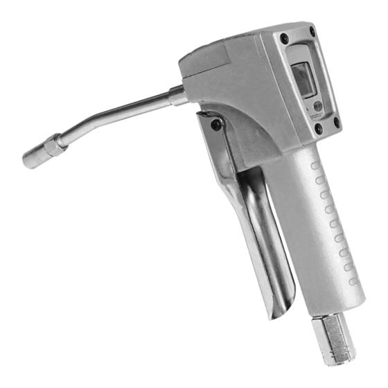
Digital Grease Control Valve
Instruction Manual
WARNING:
Read carefully and understand all INSTRUCTIONS before operating. Failure to follow the safety
rules and other basic safety precautions may result in serious personal injury.
Save these instructions in a safe place and on hand so that they can be read when required.
Keep these instructions to assist in future servicing.
REV 01/26/22
Advertisement
Table of Contents

Related Manuals for Macnaught GCVD-001


Summary of Contents for Macnaught GCVD-001
- Page 1 Digital Grease Control Valve Instruction Manual WARNING: Read carefully and understand all INSTRUCTIONS before operating. Failure to follow the safety rules and other basic safety precautions may result in serious personal injury. Save these instructions in a safe place and on hand so that they can be read when required. Keep these instructions to assist in future servicing.
-
Page 2: General Safety Regulations
GENERAL SAFETY REGULATIONS WARNING: The warnings, cautions, and instructions discussed in this instruction manual cannot cover all possible conditions or situations that could occur. It must be understood by the operator that common sense and caution are factors that cannot be built into this product, but must be supplied by the operator. -
Page 3: Technical Details
TECHNICAL DETAILS Item No. GCVD-001 Inlet Connection 1/4" NPT Pressure Range 8700psi Precision ±2% Power Source 2*AA size (1.5V) Warning Symbol WARNING: This symbol alerts you to the possibility of serious injury or death if you do not follow the instructions. -
Page 4: Installation
Toxic fluid hazard Hazardous fluid or toxic fumes can cause serious injury or death if splashed in the eyes or on the skin, inhaled, or swallowed. 1. Know the specific hazards of the fluid you are using. 2. Store hazardous fluid in an approved container. Dispose of the hazardous fluid according to all local, state and national guidelines. - Page 5 1.2 Pre-installation process 1.2.1 Warning: To reduce the risk of serious injury, the pressure release should be concerned. Please refer to 3.2 for the release process. 1.2.2 Process - Turn off the air check valve 1 as picture 1. - Effective grounding to grease supply system. Don’t use an insulation material to the ground. See 1.4 for he method for grounding.
- Page 6 1.4. Grounding 1.4.1 The grounding is to maintain the security system. 1.4.2 To reduce static electricity, each unit of the system should carry out effective grounding. - Control valve is done by manufacturers’ recommendation. - Air and fluid hoses need effective grounding too. - Air compressor is done by manufacturers’...
- Page 7 2.2.5 Automatically fixed coefficients: Press the “sw1” for 1s , the 1 section will display “0.00L”, Use the standard grease pump to transfer until grease empty, 1 section digit will display “x.xxL”; Press “SW2” for more than 3S to enter the parameter setting model, then 1 section appear “00x.xxL”;...
- Page 8 F.3 Battery replacement F.3.1When the LCD panel displays nothing or alarms from 2 section battery indication, the battery should be considered to be replaced. F.3.2 Turn on the battery cover with opener. F.3.3 Picked out of the two batteries. F.3.4 Put the new batteries into it and the polar should be concerned. F.3.5 Cover the battery.
-
Page 9: Troubleshooting Guide
TROUBLESHOOTING GUIDE Table 4: Troubleshooting Guide Trouble Reason Solution Grease leakage from Damage of top clubs 22 or steel Replace top clubs or steel ball trigger ball 30 Grease leakage from Loose connection 1 Re-tighten it bottom Grease leakage from the Wear of sealing ring 25 Replace it upper... -
Page 10: Limited Warranty
Others 1) Transportation When the control valve in transit, It should be avoided direct sunlight, the rain, the falling, the erosive substance touched and being gathered. 2) Storage 1. Storage temperature: From -10°C to +40°C. 2. The storage period is 6 months. 3. - Page 12 Macnaught Americas (813) 628-5506 | info@macnaughtusa.com * Read Manual Before Use!
Need help?
Do you have a question about the GCVD-001 and is the answer not in the manual?
Questions and answers