Table of Contents
Advertisement
Quick Links
User's
Model VJTK
Limit Alarm
Manual
for Thermocouple Input
Thank you for purchasing the JUXTA Signal Conditioner.
Please read through this manual before use for correct handling.
CAUTIONARY NOTES FOR SAFE USE OF THE
PRODUCT
This User's Manual should be carefully read before installing and
operating the product. Please keep this User's Manual for future
reference.
For more information of the safety precautions, please refer to the
"Precautions on the Use of the JUXTA Series (IM 77J01A00-91Z1)".
The related manuals and general specifications are shown in the
table below.
Doc. Name
Precautions on the Use of the JUXTA Series (User's Manual) IM 77J01A00-91Z1
Model VJTK Limit Alarm for Thermocouple Input
(User's Manual)
Model VJTK Limit Alarm for Thermocouple Input
(General Specifications)
User's manuals in the above table are essential parts of the
product; keep it in a safe place for future reference.
This manual is intended for the following personnel;
•
Engineers responsible for installation, wiring, and maintenance
of the equipment.
•
Personnel responsible for normal daily operation of the
equipment.
The following symbol is used on the product and in this manual to
ensure safe usage.
WARNING
Calls attention to actions or conditions that could
cause serious or fatal injury to the user, and indicates
precautions that should be taken to prevent such
occurrences.
CAUTION
Calls attention to actions or conditions that could
cause injury to the user or damage to the instrument
or property and indicates precautions that should be
taken to prevent such occurrences.
QR Code
The product has a QR Code pasted for efficient plant
Maintenance work and asset information management.
It enables confirming the specifications of purchased products
and user's manuals.
For more details, please refer to the following URL.
https://www.yokogawa.com/qr-code
* QR Code is a registered trademark of DENSO WAVE
INCORPORATED.
CHECKING THE PRODUCT SPECIFICATIONS
AND THE CONTENTS OF THE PACKAGE
(1) Model and Specifications Check
Check that the model and specifications indicated on the nameplate
attached to the side face of the main unit are as ordered.
(2) Contents of the Packing
Check that the package contains the following items:
•
VJTK: 1
Standard Accessories:
•
Tag number label: 1 sheet
•
Range label: 1 sheet
IM77J01T21-01E
5th Edition June 2022 (YK)
Doc. Number
IM77J01T21-01E
(This manual)
GS 77J01T21-01E
1
2-9-32, Naka-cho Musashino-shi, Tokyo 180-8750 Japan
You can download the latest manuals from the following website:
http://www.yokogawa.com/ns/juxta/im/
•
RJC sensor: 1
•
User's manual (IM 77J01T21-01E, this manual): 1 copy
•
User's manual (IM 77J01A00-91Z1): 1 copy
GENERAL
This plug-in type Limit Alarm for thermocouple input receives
thermocouple signal.
•
Each parameter setting can be changed using a PC (VJ77
PC-based Parameters Setting Tool).
MODEL AND SUFFIX CODES
Model
Suffix codes
VJTK
-0 2
x -x T 0
Fixed
-0
code
Output
2
configuration
6
Power supply
7
-1
-2
-3
-4
-5
Input signal
-6
-7
-8
-9
-A
Output signal
T
Fixed code
0
Fixed code
Option
*1: Operating range: 85 to 264V AC/DC
*2: Operating range: 12 to 36V DC
*3: DC voltage signal or DC current signal
1.
MOUNTING METHODS
CAUTION
● Plug/disconnect the main unit into/from the
socket vertically to the socket face. Otherwise the
terminals may bend and it may cause bad contact.
● The converter shall not tilt 5 degrees or more in
either direction when installed.
● When the converter is not connected to the socket,
it is necessary to protect the socket against ingress
of dust to the connector part.
● Keep this product in a conductive bag when
plugged out, during transport or storage.
Description
Limit Alarm for Thermocouple
0 /x
Input
Always -0
2 outputs
100-240 V AC/DC
*1
15-30 V DC
*2
K (CA)
T (CC)
E (CRC)
J (IC)
R
S
B (RH)
N
W3
W5
Alarm output (2 relay contacts)
Always 0
0
Always 0
/SN No socket (with socket if not specified)
/C0 HumiSeal coating
/FB Fuse bypass
/DF Fahrenheit display function
Advertisement
Table of Contents

Related Manuals for YOKOGAWA JUXTA VJTK


Summary of Contents for YOKOGAWA JUXTA VJTK
- Page 1 2-9-32, Naka-cho Musashino-shi, Tokyo 180-8750 Japan You can download the latest manuals from the following website: Thank you for purchasing the JUXTA Signal Conditioner. http://www.yokogawa.com/ns/juxta/im/ Please read through this manual before use for correct handling. IM77J01T21-01E 5th Edition June 2022 (YK) •...
- Page 2 ● Use of the product ignoring the specifications may 1.1 Wall Mounting cause overheating or damage. Before turning on Loosen the main unit-fixing screw to disconnect the main unit the power, ensure the following: from the socket. Next, anchor the socket onto the wall with • Power supply voltage and input signal value screws.
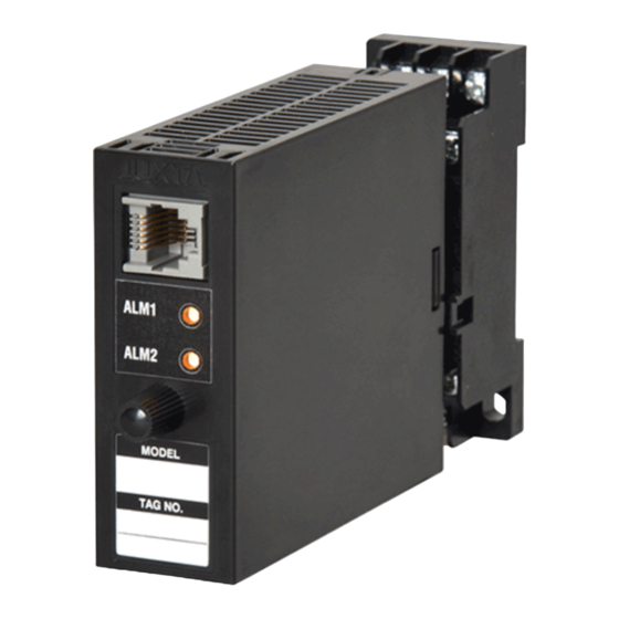
- Page 3 5.1 Settings Related to Input DESCRIPTION OF FRONT PANEL AND CONNECTION OF SETTING TOOLS 5.1.1 Input Type and Temperature Unit Select the thermocouple type to use from among K, T, E, J, R, 4.1 Front Panel S, B, N, W3 and W5 in [D08: TC TYPE]. Select the temperature unit to use in [D21: UNIT].
- Page 4 5.2.3 Hysteresis DESCRIPTION OF ALARM ACTIONS Set the alarm-1 and alarm-2 hysteresis in [E07: This chapter describes examples of alarm actions under the HYSTERESIS1] and [E08: HYSTERESIS2]. Hysteresis is a following conditions. value added to the alarm setpoint in order for an alarm status to be released (to normal) after the alarm status has been Alarm 1 Alarm 2...
- Page 5 Tag No. SELF CHK Self-check result 8.1 Calibration Apparatus DISPLAY1 Display 1 • A voltage and current generator (YOKOGAWA GS200 or the INPUT1 Input value 1 equivalent): 1 OUTPUT1 Output value 1 • Digital Multimeter (YOKOGAWA 7561 or equivalent): 1...
- Page 6 Blank Page...
Need help?
Do you have a question about the JUXTA VJTK and is the answer not in the manual?
Questions and answers