Table of Contents
Advertisement
Available languages
Available languages
Quick Links
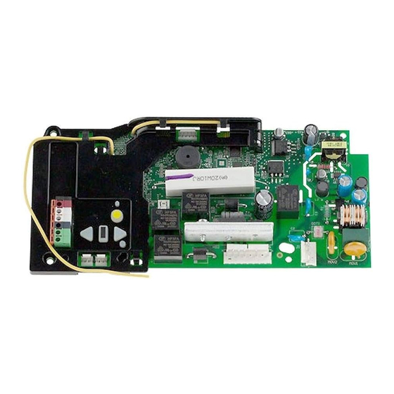
Receiver Logic Board Replacement
Model 050DCJCWFSD
To prevent possible SERIOUS INJURY or DEATH:
• Disconnect ALL electric and battery power BEFORE performing ANY
service or maintenance.
To prevent damage to the receiver logic board, DO NOT touch printed
circuit board of replacement receiver logic board during installation.
ALWAYS wear protective gloves and eye protection when changing the
battery or working around the battery compartment.
WARNING: This product can expose you to chemicals including
lead, which are known to the State of California to cause cancer or
birth defects or other reproductive harm. For more information go
to www.P65Warnings.ca.gov
NOTICE: This device complies with Part 15 of the FCC rules and Industry Canada's license-
exempt RSSs. Operation is subject to the following two conditions: (1) this device may not
cause harmful interference, and (2) this device must accept any interference received, including
interference that may cause undesired operation.
Any changes or modifications not expressly approved by the party responsible for compliance
could void the user's authority to operate the equipment.
This device must be installed to ensure a minimum 20 cm (8 in.) distance is maintained between
users/bystanders and device.
This device has been tested and found to comply with the limits for a Class B digital device,
pursuant to part 15 of the FCC rules and Industry Canada ICES standard. These limits are
designed to provide reasonable protection against harmful interference in a residential
installation. This equipment generates, uses and can radiate radio frequency energy and, if not
installed and used in accordance with the instructions, may cause harmful interference to radio
communications. However, there is no guarantee that interference will not occur in a particular
installation. If this equipment does cause harmful interference to radio or television reception,
which can be determined by turning the equipment off and on, the user is encouraged to try to
correct the interference by one or more of the following measures:
• Reorient or relocate the receiving antenna.
• Increase the separation between the equipment and receiver.
• Connect the equipment into an outlet on a circuit different from that to which the receiver is
connected.
• Consult the dealer or an experienced radio/TV technician for help.
Before you begin.
Your garage door opener has an internal gateway
located on the receiver logic board. After intalling the new receiver logic board, use the
MyQ
®
serial number found on the provided label to add your garage door opener to
your MyQ
®
account. The products illustrated in the instructions are for reference. Your
product may look different.
SERIAL NUMBER / NUM. DE SÉRIE / NUM. DE SERIE
FCC ID:
IC: 2666A -
IFETEL Cert no.:
MAC ADDRESS / ADRESSE MAC / DIRECCIÓN MAC
CONTAINS / CONTENIR / CONTENER :
PART NO. / NUM. DE PIÈCE / NOM. DE PART: DATE / FECHA:
FCC ID:
IC:
1.
Disconnect power.
3.
Remove the battery cover.
Disconnect the battery (optional
accessory). Remove the battery
and set aside (B).
4.
5.
1
2.
Open the front panel (A).
6.
Unplug the wire harnesses from the
receiver logic board (E).
7.
Remove the four screws securing
the receiver logic board, remove and
discard (F).
Label wires for reinstallation.
Disconnect the wires from the
quick connect terminals (C).
Remove the receiver logic board
cover (D).
8.
Install the receiver logic board
and connect the wire harnesses.
Ensure the wire harnesses are
connected properly. Route the
antenna through the channel in the
cover. Install receiver logic board
cover.
9.
To maintain your warranty, place
the provided label over the existing
label on the end panel of the
garage door opener (D).
10.
Reconnect the wires to the quick
connect terminals (C).
11.
Install the battery (optional
accessory) and connect the
battery connectors. Install the
battery cover.
12.
Reconnect power.
13.
Reprogram the travel and test the
safety reversal system (see pages
2 and 3).
14.
Program any accessories you may
have such as remote controls,
keyless entries or MyQ Remote
LED Lights (see page 4).
15.
Use the MyQ app to add the
new MyQ serial number to your
account.
Advertisement
Table of Contents

Related Manuals for MyQ 050DCJCWFSD

Summary of Contents for MyQ 050DCJCWFSD
- Page 1 MyQ Remote LED Lights (see page 4). SERIAL NUMBER / NUM. DE SÉRIE / NUM. DE SERIE FCC ID: Use the MyQ app to add the IC: 2666A - new MyQ serial number to your account. IFETEL Cert no.: MAC ADDRESS / ADRESSE MAC / DIRECCIÓN MAC...
-
Page 2: Program The Travel
Adjustment Program the Travel Travel limits regulate the points at which the door will stop when moving up or down. Button While programming, the UP and DOWN buttons can be used to move the Adjustment Without a properly installed safety reversal system, persons (particularly door as needed. -
Page 3: Test The Safety Reversal System
Adjustment Test the Safety Reversal System Test With the door fully open, place a 1-1/2 inch (3.8 cm) board (or a 2x4 laid flat) on the floor, centered under the garage door. Without a properly installed safety reversal system, persons Operate the door in the down direction. -
Page 4: Remote Control
30 seconds. LEARN Visor Clip Press the remote control button programmed in step 2 until the MyQ Remote LED light flashes or two clicks are heard. Program a 877MAX keyless entry pin using the LEARN button on the operator. -
Page 5: Avant De Commencer
Après avoir installé la Reprogrammer la course et tester raccordement rapide (C). nouvelle carte logique du récepteur, se servir du numéro de série MyQ sur l’étiquette ® le système d’inversion de sécurité fournie pour ajouter votre ouvre-porte de garage à votre compte MyQ. - Page 6 Réglage Programmation de la course Bouton Le réglage de fin de course fixe les points où la porte s’arrêtera lors de fléché vers son ouverture ou de sa fermeture. le haut Durant la programmation, les boutons fléchés peuvent être utilisés pour Sans un système d’inversion de sécurité...
-
Page 7: Essai Du Protector System
Réglage Essai du système d’inversion de sécurité Test La porte étant entièrement ouverte, placer une planche de 3,8 cm (1 1/2 po) d’épaisseur (ou un 2 x 4 à plat) sur le sol, centrée sous la Sans un système d’inversion de sécurité bien installé, des personnes porte de garage. - Page 8 D’apprentissage Enfoncer le bouton de la télécommande programmé à l’étape 2 jusqu’à Agrafe de ce que la lampe à DEL télécommandée MyQ clignote ou que deux clics pare-soleil se fassent entendre. Programmer un NIP d’entrée sans clé pour l’accessoire 877MAX en utilisant le D’APPRENTISSAGE sur l’actionneur.
-
Page 9: Antes De Comenzar
3). de conexión rápida (C). receptor, use el número de serie de ® MyQ que se encuentra en la etiqueta provista para Retire la cubierta del tablero Programe cualquier accesorio que agregar el abre-puertas de garaje a su cuenta de ®... - Page 10 Ajustes Programación del recorrido Los límites de desplazamiento regulan los puntos en los que la puerta se Botón UP detendrá al abrirse y cerrarse. (ARRIBA) Cuando programar, los botones de arriba y abajo pueden utilizarse para mover la puerta cuando sea necesario. Si el sistema de reversa de seguridad no se ha instalado debidamente, Botón Ajuste las personas (y los niños pequeños en particular) podrían sufrir...
- Page 11 Ajustes Pruebe el sistema de reversa de seguridad. Prueba Con la puerta completamente abierta, coloque una tabla de 3.8 cm (1 1/2 de pulg.) de altura (o de 5 x 10 cm [2 x 4 pulg.] acostada en el Si el sistema de reversa de seguridad no se ha instalado debidamente, piso), centrada abajo de la puerta del garaje.
-
Page 12: Control Remoto
Presione el botón del control remoto programado en el paso 2 hasta visera que la luz remota LED MyQ parpadee o se escuche dos clics. Programe el PIN de una llave digital 877MAX usando el botón APRENDIZAJE, en el operador.
Need help?
Do you have a question about the 050DCJCWFSD and is the answer not in the manual?
Questions and answers