Table of Contents
Advertisement
Quick Links
INSTALLATION MANUAL AND
OPERATING INSTRUCTIONS
MD41-( ) Series GPS ANNUNCIATION CONTROL UNIT
MD41-328
MD41-338
MD41-324
MD41-334
MID-CONTINENT INST. CO., INC
FOR ALLIED SIGNAL KLN 90B
28vdc
Horizontal Mount
28vdc
Vertical Mount (shown on page 13)
14vdc
Horizontal Mount
14vdc
Vertical Mount (shown on page 13)
MANUAL NUMBER 7016074
Advertisement
Table of Contents

Subscribe to Our Youtube Channel
Related Manuals for Mid-Continent Instruments MD41 Series

Summary of Contents for Mid-Continent Instruments MD41 Series
- Page 1 INSTALLATION MANUAL AND OPERATING INSTRUCTIONS MD41-( ) Series GPS ANNUNCIATION CONTROL UNIT FOR ALLIED SIGNAL KLN 90B MD41-328 28vdc Horizontal Mount MD41-338 28vdc Vertical Mount (shown on page 13) MD41-324 14vdc Horizontal Mount MD41-334 14vdc Vertical Mount (shown on page 13) MID-CONTINENT INST.
- Page 2 MANUAL REVISION AND HISTORY MANUAL: MD41-324, -334, -328, -338 REVISION: OCT. 25, 1995 Rev. 1 MANUAL NUMBER: 7016074 This revision level of this manual consist of the following changes: Add MD41-334, -338 vertical mount versions. REVISION: NOV. 06, 1995 Rev. 2 Add MD41-328(5V)/338(5V) These part numbers have 5 volt push-button lighting.
- Page 3 TABLE OF CONTENTS SECTION 1 GENERAL DESCRIPTION INTRODUCTION SPECIFICATIONS, TECHNICAL 1.2.1 PHYSICAL CHARACTERISTICS 1.2.2 ENVIRONMENTAL CHARACTERISTICS 1.2.3 SPECIFICATIONS, ELECTRICAL 1.2.4 FRONT PANEL CONTROLS AND ANNUNCIATIONS 1.2.4.1 CONTROLS 1.2.4.2 ANNUNCIATIONS 1.2.5 INTERFACE 1.2.6 EQUIPMENT LIMITATIONS 1.2.7 MAJOR COMPONENTS SECTION 2 INSTALLATION CONSIDERATIONS COOLING EQUIPMENT LOCATION ADDITIONAL ANNUNCIATIONS...
-
Page 4: Section 1 General Description
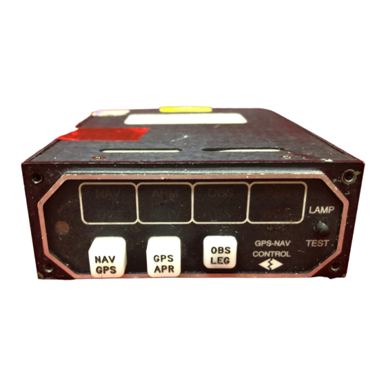
SECTION 1 GENERAL DESCRIPTION INTRODUCTION The MD41-( ) is a self -contained GPS Annunciation and Control unit. It combines all the necessary functions required for switching HSI/CDI data inputs between a conventional NAV (VOR) receiver and the Allied Signal KLN 90B approach-certified GPS receiver. In addition, the MD41-( ) contains several GPS status annunciations used to indicate modes selected by the front panel switches and various inputs from the GPS receiver. -
Page 5: Environmental Characteristics
1.2.2 ENVIRONMENTAL CHARACTERISTICS TSO Compliance: TSO C129 Applicable Documents: RTCA DO-160C, DO-208 Operating Temperature Range: -55°C to +70°C Humidity: 95% Non-Condensing Altitude Range: 0 to 55,000 ft. Vibration: Cat. M and N Operational Shock: Rigid Mounting, 6 G Operational 15 G Crash Safety. 1.2.3 SPECIFICATIONS, ELECTRICAL Design:... - Page 6 This will activate the course selector and also disable the automatic GPS waypoint sequencing to the next leg. This will disable the course selector input to the GPS and will enable automatic GPS waypoint sequencing to the next leg of the pre-planned route. GPS message alert, from the GPS receiver.
-
Page 7: Equipment Limitations
1.2.6 EQUIPMENT LIMITATIONS The MD41-( ) series control units contain specific dash numbers to be used with various GPS receivers. The installer must match the correct controller part number with the GPS receiver being installed. The conditions and tests required for TSO approval of this article are minimum performance standards. -
Page 8: Section 2 Installation Considerations
SECTION 2 INSTALLATION CONSIDERATIONS COOLING No direct cooling is required. As with any electronic equipment, overall reliability may be increased if the MD41-( ) is not located near any high heat source or crowded next to other equipment. Means of providing a gentle air flow will be a plus. EQUIPMENT LOCATION The MD41-( ) must be mounted as close to the pilot’s field of view as possible. -
Page 9: Section 3 Installation Procedures
SECTION 3 INSTALLATION PROCEDURES GENERAL INFORMATION This section contains interconnect diagrams, mounting dimensions and other information pertaining to the installation of the MD41-( ). After installation of cabling and before installation of the equipment, ensure that power is applied only to the pins specified in the interconnect diagram. - Page 10 REAR VIEW OF J1 (bottom) CONNECTOR PIN NO. 1 ---------------- NO7 RELAY 2 ---------------- NC7 RELAY 3 ---------------- ILS ENERGIZE TO AUTOPILOT 4 ---------------- ILS FROM NAV (VOR) REC (for autopilot) 5 ---------------- C8 RELAY 6 ---------------- NC8 RELAY 7 ---------------- NO8 RELAY 8 ---------------- GPS APR ACTV ANNUNCIATION 9 ---------------- OBS HOLD (logic low to GPS) 10 --------------...
- Page 11 Note 1: All relays shown in NAV position. FIGURE 3-2 SCHEMATIC PINOUT, 50 PIN DSUB REV. 4 Jan. 09, 1997...
-
Page 12: Actual Size
MD156 Front Mounting Plate. Optional, must be ordered from Mid- Continent Inst. ACTUAL SIZE Note 1: Use four 4-40 X 3/8 to 1.0” Flat Head Phillips Screws for Mounting, MCI PN 7016165 (supplied). MD155 punch is available for hole cutout. FIGURE 3-3 CUTOUT DIMENSIONS FOR PANEL MOUNTING REV. - Page 13 FIGURE 3-4 OUTLINE DRAWING REV. 4 Jan. 09, 1997...
- Page 14 FIGURE 3-5 WIRING DIAGRAM, MD41-324/334 KLN 90B (14V) REV. 4 Jan. 09, 1997...
- Page 15 FIGURE 3-6 WIRING DIAGRAM, MD41-328/338/328(5V)/338(5V) KLN 90B (28V) REV. 4 Jan. 09, 1997...
-
Page 16: Section 4 Post Installation Checkout
SECTION 4 POST INSTALLATION CHECKOUT PRE INSTALLATION TESTS With the MD41-( ) disconnected, turn on the avionics master switch and verify that aircraft power is on pin 12 for 14VDC systems and pin 13 for 28VDC systems. Using an ohm meter, verify pin 25 is aircraft ground. -
Page 17: Environmental Qualification Form
ENVIRONMENTAL QUALIFICATION FORM RTCA / DO160C NOMENCLATURE: MD41-( ) GPS ANNUNCIATION CONTROL UNIT MODEL NO: MD41-( ) TSO NO: C129 CLASS A1 MANUFACTURER TEST SPECIFICATION: MPS 7015613 MANUFACTURER: MID-CONTINENT INSTRUMENT CO., INC. 9400 E. 34 WICHITA, KS 67226 PHONE (316) 630-0101 Conditions Section Description of Conducted Tests... - Page 18 Environmental Qualification (cont.) Conditions Section Description of Conducted Tests Sand and Dust 12.0 Equipment identified as Category X, no test required Fungus 13.0 Equipment identified as Category X, no test required Salt Spray 14.0 Equipment identified as Category X, no test required Magnetic Effect 15.0 Equipment tested to Class Z...
Need help?
Do you have a question about the MD41 Series and is the answer not in the manual?
Questions and answers