Table of Contents
Advertisement
INSTALLATION MANUAL AND
OPERATING INSTRUCTIONS
MD41-( ) Series GPS Annunciation Unit
For Garmin GNS 430/430W/530/530W VHF
Communication and Navigation Management System
MD41-1484W
MD41-1488W
MD41-1494W
MD41-1498W
MID-CONTINENT INST. CO., INC
14VDC
Horizontal Mount
28VDC
Horizontal Mount
14VDC
Vertical Mount
28VDC
Vertical Mount
MANUAL NUMBER 9016478
Advertisement
Table of Contents

Subscribe to Our Youtube Channel
Related Manuals for Mid-Continent Instruments MD41 Series

Summary of Contents for Mid-Continent Instruments MD41 Series
- Page 1 INSTALLATION MANUAL AND OPERATING INSTRUCTIONS MD41-( ) Series GPS Annunciation Unit For Garmin GNS 430/430W/530/530W VHF Communication and Navigation Management System MD41-1484W 14VDC Horizontal Mount MD41-1488W 28VDC Horizontal Mount MD41-1494W 14VDC Vertical Mount MD41-1498W 28VDC Vertical Mount MID-CONTINENT INST. CO., INC MANUAL NUMBER 9016478...
- Page 2 Revision History Rev. Date Detail 01/19/07 Initial release. 02/15/07 J1 connector was 9016475, now 9016479. 03/12/07 Corrected section 4.1 to show proper pins, corrected mating connector rear view. 4/24/07 Correct connector schematic pinout in section 4828 1.2.5. Add –1494W and –1498W versions. REV.
-
Page 3: Table Of Contents
TABLE OF CONTENTS SECTION 1 GENERAL DESCRIPTION INTRODUCTION SPECIFICATIONS, TECHNICAL 1.2.1 PHYSICAL CHARACTERISTICS 1.2.2 ENVIRONMENTAL CHARACTERISTICS 1.2.3 SPECIFICATIONS, ELECTRICAL 1.2.4 FRONT PANEL CONTROLS AND ANNUNCIATIONS 1.2.4.1 CONTROLS 1.2.4.2 ANNUNCIATIONS 1.2.5 INTERFACE 1.2.6 EQUIPMENT LIMITATIONS 1.2.7 MAJOR COMPONENTS SECTION 2 INSTALLATION CONSIDERATIONS COOLING EQUIPMENT LOCATION ROUTING OF CABLES... -
Page 4: Physical Characteristics
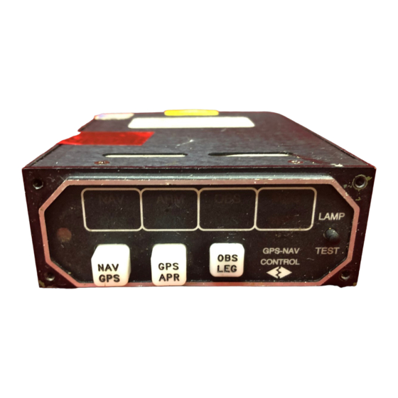
SECTION 1 GENERAL DESCRIPTION INTRODUCTION The MD41-( ) is a compact, self-contained GPS Annunciation unit. This unit displays status annunciation received from the Garmin GNS 430/430W/530/530W series GPS navigation management systems. Features include dual 20,000 hour lamps used for all annunciations along with automatic photocell dimming. -
Page 5: Front Panel Controls And Annunciations
1.2.3 ELECTRICAL SPECIFICATIONS Design All Solid State MD41-1484W (14VDC) 0.30 Amps MD41-1488W (28VDC) 0.25 Amps MD41-1494W (14VDC) 0.30 Amps MD41-1498W (28VDC) 0.25 Amps 1.2.4 FRONT PANEL CONTROLS AND ANNUNCIATIONS 1.2.4.1 ANNUNCIATIONS VLOC NAV or ILS information presented on the HSI or CDI GPS information presented on the HSI or CDI ON indicates message(s) active. -
Page 6: Equipment Limitations
1.2.6 EQUIPMENT LIMITATIONS The MD41-( ) series control units contain specific dash numbers to be used with various GPS receivers or Navigation Management Systems. The installer must match the correct controller part number with the system being installed. The conditions and tests required for TSO approval of this article are minimum performance standards. -
Page 7: Installation Considerations
SECTION 2: INSTALLATION CONSIDERATIONS COOLING No direct cooling is required. As with any electronic equipment, overall reliability may be increased if the MD41-( ) is not located near any high heat source or crowded next to other equipment. Means of providing a gentle airflow will be a plus. EQUIPMENT LOCATION The MD41-( ) must be mounted as close to the pilot’s field of view as possible. -
Page 8: General Information
SECTION 3: INSTALLATION PROCEDURES GENERAL INFORMATION This section contains interconnect diagrams, mounting dimensions and other information pertaining to the installation of the MD41-( ). After installation of cabling and before installation of the equipment, ensure that power is applied only to the pins specified in the interconnect diagram. -
Page 9: Installation Limitations
INSTALLATION LIMITATIONS Wire the aircraft harness according to figure 3-3. Use at least 24 AWG wire for all connections. Avoid sharp bends and routing cable near high-energy sources. Care must be taken to tie the harness away from aircraft controls and cables. Normal installation techniques should be applied. - Page 10 15-pin High Density D-Sub 2.392 MAX 0.150 0.150 0.750 0.375 0.150 2.150 2.450 2.150 2.450 0.375 0.750 MD41-1484W, MD41-1488W MD41-1494W, MD41-1498W FIGURE 3-2 OUTLINE DRAWING REV. C April 24, 2007...
-
Page 11: Instrument Panel Mounting
FIGURE 3-3 INSTRUMENT PANEL MOUNTING REV. C April 24, 2007... - Page 12 MD41-( ) ACU TO MD41-ACU AIRCRAFT PWR CIRCUIT BREAKER POWER GND APR ANN P4001 TERM ANN GNS 430/430W WPT ANN P5001 MSG ANN GNS 530/530W VLOC ANN GPS ANN INTG ANN LAMP TEST NOTES: 1) REFER TO GARMIN GNS 430, 430W or GNS 530, 530W INSTALLATION MANUAL FOR ACTUAL INSTALLATION.
-
Page 13: Post Installation Checkout
SECTION 4: POST INSTALLATION CHECKOUT PRE INSTALLATION TESTS With the MD41-( ) disconnected, turn on the avionics master switch and verify that aircraft power is on pin 5. Using an ohmmeter, verify pin 15 is aircraft ground. OPERATING INSTRUCTIONS Turn off the avionics master switch and connect the mating connector to the rear of the MD41-( ). - Page 14 DO-160C Environmental Qualification Form NOMENCLATURE: Annunciation Control Unit (ACU) MODEL NUMBER: MD41-( ) Series TSO NUMBER: C129, Class A1 MANUFACTURERS SPECIFICATIONS: Minimum Performance Specification 7015613 Test Data Specification (TDS) 161, dated 2/12/07 MANUFACTURER: Mid-Continent Instrument Co., Inc. ADDRESS: DESCRIPTION OF TEST CONDITIONS SECTION Temperature and Altitude...
Need help?
Do you have a question about the MD41 Series and is the answer not in the manual?
Questions and answers