Advertisement
- 1 Hints and tips
- 2 Warnings
- 3 Specifications
- 4 Components
- 5 Indoor base station (receiver) features
- 6 Touch buttons
- 7 Temperature & humidity trend
- 8 Outdoor remote sensor (transmitter) features
- 9 Buttons
- 10 Battery installation and setup
- 11 Synchronize remote sensors with the base Station
- 12 Place the base station and remote sensor
- 13 Maximum & minimum recorded temperature & humidity
- 14 FCC statement of compliance
- 15 Limited one-year warranty
- 16 Purchasing additional remote sensors
- 17 Customer service
- 18 Documents / Resources
Hints and tips
If the receiver does not connect to the transmitter, try the following:
- Press and hold the CHANNEL/SYNC button on the base station and then press TX button on the transmitter.
- Relocate the base station and/or the remote unit until connection is found.
- Signals from other electronic devices may cause interference. Place the base station and receiver away from these devices.
- The transmitter may not function properly in extreme temperatures due to battery power. Replace the batteries or the unit will resume proper function in more moderate weather.
- If the base station is attached to a refrigerator or a metal object by magnet, the transmission may be shorter. Remove the base station from the refrigerator or the metal object or place the base station and remote sensor as close as possible.
- If the Humidity is lower than 10%, it will display LLL.
Warnings
- Do not subject the unit to excessive force, shock, dust, temperature or humidity.
- Do not immerse the unit in water.
- Do not remove any screws.
- Do not dispose this unit in a fire. IT MAY EXPLODE.
- Keep unit away from small children. The unit or parts of the unit might be a choking hazard.
- Never attempt to recharge the batteries using any other methods.
- Dispose of the unit legally and recycle when possible.
Specifications
- 433 Mhz transmission frequency
- Transmission range up to 200 feet in open area. (range maybe shorter based on interference present)
- Indoor Temperature range: -4°F ~ 158°F (-20°C ~ 70°C)
- Outdoor Temperature range: -58°F ~ 158°F (-50°C ~ 70°C)
- Humidity range: 10% ~ 99%
- Temperature tolerance: +/- 2.0°F (+/- 1.1°C)
- Humidity tolerance: ±2% from 30% to 80%; ±3% below 30% and above 80%
- Power: 2 X AAA 1.5V for base unit and 2 X AAA 1.5V for remote sensor
Components
- One base station unit (Receiver)
- One remote sensor (Transmitter)
*Although the remote sensor is designed to be rain-proof, the remote sensor must be always placed upwards so that rain won't get inside the sensor through the vent holes on the bottom of the senor which functions to let the remote sensor detect the environmental temperature and humidity more precisely and quickly.
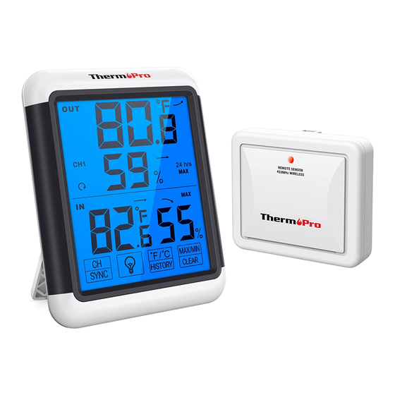
Indoor base station (receiver) features
 features")
- LCD display: Displays the current outdoor humidity/temperature and indoor humidity/temperature
- Battery Compartment: Holds 2 AAA batteries to power the unit
- Tabletop and wall-mounted design
- Indoor Temperature range: -4°F ~ 158°F (-20°C ~ 70°C).
- Humidity range: 10% ~ 99%.
- Temperature display unit: °C and °F selectable
- Temperature Resolution: 0.1°C/°F
- Humidity Resolution: 1%
- Low battery indication
- Four touch buttons
- Backlight
Touch buttons
CHANNEL/SYNC: Press once to display the temperature and humidity readings from up to 3 outdoor remote sensors; Press and hold this button to enter the synchronization mode.
MAX/MIN/CLEAR: Touch once to display the maximum or minimum temperature and humidity; Press and hold to clear the history data.
°F/°C/History: Press to select the temperature display in ºC or ºF; When the display shows the maximum or minimum temperature and humidity. Touch this button once to set the maximum and minimum data record time interval between ALL TIME or 24 hours.
Note: Both ALL TIME and 24 hours represent the time since you last manually cleared the history data or installed a new battery.
![]() : Touch once to turn on/off backlight. If you do not press the button for 15 seconds, the backlight will be automatically turned off.
: Touch once to turn on/off backlight. If you do not press the button for 15 seconds, the backlight will be automatically turned off.
Temperature & humidity trend
![]() indicates the temperature & humidity is in an increasing trend.
indicates the temperature & humidity is in an increasing trend.![]() indicates the temperature & humidity is in a no change trend.
indicates the temperature & humidity is in a no change trend.![]() indicates the temperature & humidity is in a decreasing trend.
indicates the temperature & humidity is in a decreasing trend.
 indicates the temperature & humidity is in a no change trend.
Outdoor remote sensor (transmitter) features
 features")
- Battery Compartment: Holds 2 X AAA batteries to power the unit.
- Rain-proof and wall-mounted design
- Outdoor Temperature range: -58°F ~ 158°F (-50°C ~ 70°C)
- Humidity range: 10% ~ 99%
Buttons
CHANNEL Selector (1,2,3): Slide to set Channel 1,2 or 3.
RESET: Press once to reset the remote sensor.
TX: Press to send temperature/humidity data to the receiver manually.
Battery installation and setup
- Open the battery compartment of the remote sensor as below Figure;


- Slide the channel selector switch inside the battery compartment to your desired channel. For the first remote you may select any channel, for additional remotes select any unused channel;
- Insert (2) AAA batteries according to the polarity markings. Replace the battery compartment cover;
- Open the battery compartment at the back of the base station and insert (2) AAA batteries according to the polarity markings. Replace the compartment door;
Note:
Do not mix old and new batteries.
Do not mix alkaline, standard (carbon zinc), or rechargeable (nickel cadmium) batteries.
For maximum performance in normal conditions we recommend using good quality alkaline batteries.
If the battery power is low, there will be low battery icon showing on the base station display.
Synchronize remote sensors with the base Station
Please note: each time the batteries (either base station or remote sensor) are replaced or base station/remote sensor lost connection, make sure to follow the below synchronization process to pair and re-connect the base station and remote senor:
- Position the remote sensor near the base station;
- Once the batteries are installed in the base station, the RF signal icon
![]() (located on the upper left of the base station display) will flash for 3 minutes, indicating that the base station is in synchronization mode: it is waiting for remote sensors to be registered.
(located on the upper left of the base station display) will flash for 3 minutes, indicating that the base station is in synchronization mode: it is waiting for remote sensors to be registered. - If 3 minutes have passed after the batteries were installed in the base station and the RF signal Icon
![]() is no longer flashing, press and hold the CHANNEL/SYNC button of the base station for 3-4 seconds until the RF signal icon is flashing again to set it back in synchronization mode;
is no longer flashing, press and hold the CHANNEL/SYNC button of the base station for 3-4 seconds until the RF signal icon is flashing again to set it back in synchronization mode; - Install the batteries in the remote sensor and wait for a moment or just press either the TX or RESET button inside the remote sensor battery compartment, the remote sensor temperature/humidity will show on the base station display which indicates the synchronization is complete.
- If you have additional remote sensors, repeat the above steps to register the remote sensors (up to 3 remote sensors can be registered with one base station);
- If you have registered more than one sensor, press the CHANNEL/SYNC button on the base station to select the remote channel you want displayed permanently on the base station. Press CHANNEL/SYNC button until you observe a circular arrow on the base station LCD display under the channel number. The unit will then auto-scroll, changing from channel to channel every 5 seconds.
NOTE: If you have additional remote sensors, when you are synchronizing remote sensors with the base station, the unit will keep changing from channel to channel in the first three minutes, after that you can select any channel you like or auto -scroll mode.
Place the base station and remote sensor
- The indoor base station (receiver) should always be placed in a well ventilated indoor area and located away from vents, heating or cooling elements, direct sunlight, windows, doors, or any other openings.
- The remote sensor (transmitter) can be placed on a flat surface indoor or outdoor. Make sure the sensor is within the transmission distance from the base station and with minimal obstructions.
- The base station and remote sensor can both be wall mounted.
NOTE: Although the remote sensor is designed to be rain-proof, the remote sensor must be always placed upwards so that rain won't get inside the sensor through the vent holes on the bottom of the senor which functions to let the remote sensor detect the environmental temperature and humidity more precisely and quickly.
Maximum & minimum recorded temperature & humidity
- Press MAX/MIN/Clear button once to display the highest indoor and outdoor temperatures/humidity recorded since last reset. MAX is shown on the display.
- Press MAX/MIN/Clear button again to display the lowest indoor and outdoor temperatures/humidity recorded since last reset. MIN is shown on the display.
- To clear and reset the max/min records, when either the MAX or MIN record is shown on the LCD display, press and hold MAX/MIN/Clear for 3 seconds.
- When either the MAX or MIN record is shown on the LCD display, press ALL-TIME/24 button once to set the data record time interval between ALL TIME or 24 hours.
Note: Both ALL TIME and 24 hours represent the time since you last time manually cleared the history data or battery installation.
FCC statement of compliance
This device complies with Part 15 of the FCC rules. Operation is subject to the following two conditions:
1) This device may not cause harmful interference.
2) This device must accept any interference received, including interference that may cause undesired operation.

Changes or modifications to this unit not expressly approved by the party responsible for compliance could void the user's authority to operate the equipment.
NOTE: This equipment has been tested and found to comply with the limits for a Class B digital device, pursuant to Part 15 of the FCC rules. These limits are designed to provide reasonable protection against harmful interference in a residential installation. This equipment generates, uses and can radiate radio frequency energy and, if not installed and used in accordance with the instructions, may cause harmful interference to radio communications. However, there is no guarantee that interference will not occur in a particular installation. If this equipment does cause harmful interference to radio or television reception, which can be determined by turning the equipment off and on, the user is encouraged to try to correct the interference by one of more of the following measures:
- Reorient or relocate the receiving antenna.
- Increase the separation between the equipment and the receiver.
- Connect the equipment into an outlet on a circuit different from that to which the receiver is connected. Consult the dealer or an experienced radio/TV technician for help.
Limited one-year warranty
ThermoPro warrants this product to be free of defects in parts, materials and workmanship for a period of one year, from date of purchase.
Should any repairs or servicing under this warranty be required, contact Customer Service by phone or email for instructions on how to pack and ship the product to ThermoPro.
This warranty gives you specific legal rights and you may also have other rights which vary from state to state.
Purchasing additional remote sensors
The model number of the remote sensor for this unit is TPR65.
Additional sensors may be ordered directly from Amazon or ThermoPro by contacting our customer service listed below.
Customer service
Telephone: 44-203-769-1321
Email: service@buythermopro.com
Hours: Weekdays 8:00 AM- 6:00 PM EST

Documents / ResourcesDownload manual
Here you can download full pdf version of manual, it may contain additional safety instructions, warranty information, FCC rules, etc.
Advertisement


Need help?
Do you have a question about the TP-65 and is the answer not in the manual?
Questions and answers