Advertisement
Quick Links
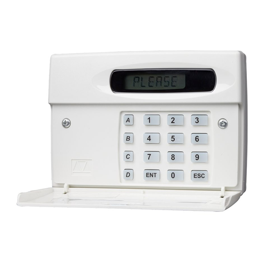
SD1+ Installation & User Guide
Connections
The SD1+ is connected between the alarm control
panel and the telephone line. It behaves like another
extension to the telephone and does not affect its
normal operation or that of any other extension fitted.
The unit requires no batteries as its power and mains fail
back-up are derived from the alarm control panel.
The SD1+ can accept up to four trigger inputs these
correspond to the messages (A, B, C and D) that the
SD1+ sends out and should be recorded as such. If the
control panel does not have a fire monitoring capability
then the SD1+ will accept a direct connection from a
suitable smoke alarm. Trigger inputs can be selected as
+ve or -ve applied. The SD1+ may also be included in
the control panel tamper circuit.
Passcode
The SD1+ requires a passcode to be entered to gain
access to all of the programming menus, this code can
also be used to cancel an activation if the unit has been
accidentally triggered.
Passcode Type
The passcode that is required by the SD1+ to enter into
the programming menus, can be modified so that it is a
standard 4 digit code, a 4 digit code followed by the
enter key, a standard 6 digit code, or a 6 digit code
followed by the enter key.
Programmable Output
The SD1+ has a programmable output that is capable
of supplying up to 1OOmA of current. This output can be
programmed to activate when the SD1+ has been
triggered, when the SD1+ has been successfully
acknowledged, or when the SD1+ has failed to
communicate to all telephone numbers.
496540 Issue A
Call Routing
The SD1+ can be programmed so that each trigger
input A, B, C or D will only dial a certain telephone
number. This can be used for when the dialler is
required to call four different numbers under three
different conditions e.g. trigger A will only dial
telephone number 1, trigger B will only dial telephone
numbers 2 & 3 whereas trigger C will dial telephone
numbers 1,2, 3 & 4.
Call Abort
The SD1+ can be programmed so that if it is
accidentally triggered, the call can be aborted.
Once aborted, the dialler will stop dialling out
immediately. The SD1+ can be aborted by one of the
following methods: when a signal is applied to the
abort input, when the input that triggered the unit is
removed, or when the user passcode is entered.
When an abort is performed by the code, the display
shows "ABORTED" as visual confirmation of the abort
being carried out (a chime tone will also be heard).
Last Call Log
The SD1+ has a last call log, this enables the user to
find out who the unit has dialled and who
acknowledged it. The log also shows which input was
triggered last.
Acknowledgement Options
Once the SD1+ has made its call and delivered its
message, it requires a signal to say that the message
has been successfully received. This is done by the
recipient pressing the number "8" button on their
telephone. When the SD1+ has been acknowledged,
it will shut down until it is triggered again. This option
determines how many times the unit must be
acknowledged before it shuts down.
1 of 12
SD1+
SD1+
Advertisement

Related Manuals for Menvier SD1+


Summary of Contents for Menvier SD1+
- Page 1 SD1+ SD1+ Installation & User Guide Connections Call Routing The SD1+ is connected between the alarm control The SD1+ can be programmed so that each trigger panel and the telephone line. It behaves like another input A, B, C or D will only dial a certain telephone extension to the telephone and does not affect its number.
- Page 2 SD1+ Telephone Numbers Three Way Calling The SD1+ can dial up to four different telephone This is a service that is normally provided by British numbers. These numbers can be up to 24 digits long Telecom, if this service is enabled, the SD1+ will use it to and are programmed using the LCD display and prevent anyone trying to block the telephone line.
-
Page 3: Pcb Layout
SD1+ PCB Layout Œ Ž Loudspeaker Tamper Switch TRIG INPUTS ABORT TAMP Microphone SD1+ Tamper connections (SELV) ‘ TRIGGER Trigger Inputs (SELV) POLARITY • Trigger Polarity Telephone Connections (TNV) Country Setting (Not fitted on UK product) ” O/P1 -ve 12V Supply and ’... -
Page 4: Control Panel Connections
TRIG A TRIG B TRIG C Polarity Supply + Supply - T r i g g e r Fire Alarm Type Menvier TS400/TS410 Zone 4 Zone 5 Aux + Aux - 0V app. Menvier TS510 OP 2 * OP 1 *... -
Page 5: Commissioning And Testing
SD1+ BT Connections Commissioning and Testing Remove the centre PCB screw and remove the Hold the blade of a small screwdriver between plastic cover over the telephone connection the “Factory Restart” pins (JP2) and switch the terminals. power back on to the control panel (battery and mains). - Page 6 SD1+ SD1+ Getting Started SD1+ Menu Options ???? All of the SD1+ menu options are accessed by entering the user passcode (default 1234). These menu options READY allow all the necessary programming of the SD1+ and are selected by pressing the relative “Hot Key” as shown in the table below.
- Page 7 SD1+ PLEASE Programming: Initialising The SD1+ When you power up the SD1+ for the first time, a factory RECORD restart is required. This involves shorting out the factory restart pins (JP2) whilst applying power to the unit. The display will show “PLEASE RECORD”, this indicates that the ???? memory is blank (i.e., all telephone numbers and me ssage s a re not pr og ra m m ed ) .
- Page 8 SD1+ SD1+ Programming a Pager Number ???? If the SD1+ is dialling a pager, it may have to wait before sending the paging message. This is achieved READY by entering one or more “M” (4 second waits) after the pager number. The unit also needs to be programmed to send the message correctly i.e.
- Page 9 SD1+ Testing the SD1+: Call Acknowledgment Procedure If the unit has been triggered or a test call has been sent, you must ensure that the recipient of the call is aware of the call acknowledgement procedure, so that they can successfully shut down the SD1+ and prevent it from dialling them again.
- Page 10 SD1+ exchange as a request for a new line. With a new line General Three Way Calling available, the SD1+ then attempts to dial out. If the SD1+ is connected to an older pulse dial Three Way Calling is a feature that is available from BT exchange, the numbers being dialled must be Network Services.
- Page 11 SD1+ Quick Reference: Dialler Options SD1+ ???? READY Clear By Options Numbers & Phrases Message's or test call's ENT 1-4 1-4 / ENT CLEARBY- OR 0-D TO SEND Clear By Options Program Numbers Record Messages Delete Options Send test call's Replay Message's TEL NO 1 RECORD...
- Page 12 SD1+ This page intentionally left blank 12 of 12 SD1+ 496540 Issue A...
Need help?
Do you have a question about the SD1+ and is the answer not in the manual?
Questions and answers