Table of Contents
Advertisement
Quick Links
Advertisement
Table of Contents

Related Manuals for TCS LT-50

Summary of Contents for TCS LT-50
-
Page 2: Table Of Contents
LT-50 Quick Start Guide Table of Contents What’s In The Box Specifications 3 Connections Configuration Jumpers 5 Getting Started 6 Setting Up the LT-50 Using the LT-50 7 Power On/Off 7 Menu Navigation 7 The “Help” Button 7 Programmable Buttons Maximum Number of Locos Text Entry Operations ... -
Page 3: What's In The Box
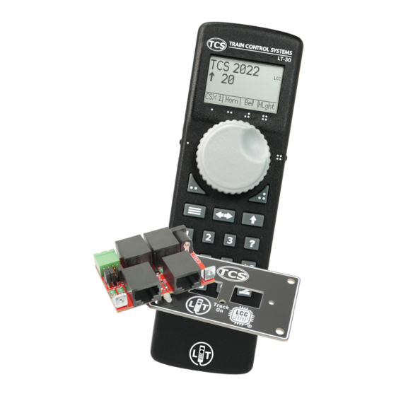
• LT Panel assembly screws (2x) • LT Panel mounting screws (4x) • 2-pin screw terminal plug (Green) for DCC Track output • Option jumpers (3x) • RJ-45 Cable (7ft/2.13M) • LT-50 power supply (15V, 36W) Specifications DCC System • 1.4A continuous, 2.8A peak current limit with soft start, configurable current limit, and load reporting •... -
Page 4: Connections
(See the graphics on the next page to see where you can find each of these connections listed on the LT-50.) “LT”: RJ-45 jack (1x) This jack must be used in order to allow the LT-50 to provide power to the track output. Using any other jack on the LT Panel with the LT- 50 will not power the track output. The fascia cover plate has been designed so that it is not possible to be screwed to the fascia board upside-down. -
Page 5: Configuration Jumpers
Configuration Jumpers Jumper Position Description Insert this jumper to add termination to the LCC-CAN bus. An LCC-CAN bus should have exactly two terminators, with one at each end of the bus. This jumper can (optional- (1) TERM ly) provide for one of the required terminators. In practical- ity, a very short (less than 10ft or 3m) LCC-CAN bus can still work reliably with one terminator. (2) N/A Not used. Insert these two jumpers to pass the low power DCC signals through the LCC panel (pins 4 & 5 of the LCC-CAN standard). (3 & 4) DCC/F Remove these jumpers to disconnect the low power DCC signals from passing through the panel. The LT Panel uses the NMRA S-9.1.2 Full Scale Interface DCC/F Simplified Diagram... -
Page 6: Getting Started
2. Plug one end of the RJ-45 cable into the jack on the LT Panel labeled with the LT logo. 3. Plug the other end of the RJ-45 cable into the bottom of the LT-50. If everything is connected properly, the LT-50 handheld will boot up in approximately 3 seconds, and the Track Power LED should go Green to indicate that track power is online. At this point, you are ready to place... -
Page 7: Using The
Using the LT-50 Power On/Off Plug the LT-50 into the LT-50 jack on the LT Panel to power up the throttle into command station mode. If you would like to use the LT-50 as a normal LCC throttle, connect it into any other LCC port. Once powered up, the throttle will display the main Drive Window - your dashboard for locomotive operations. In order to completely power down the LT-50, you must unplug it from the fascia panel board, or unplug the power supply. -
Page 8: Programmable Buttons
Menu > Settings > Roster Settings > Functions. Programmable Buttons There are nine buttons on the LT-50 that can be assigned operations by the user. These buttons can be customized to perform an operation different from their default assignment. The one, two, three, and four “dot” buttons will always identify their action with an on-screen description. If the description is blank, no action is assigned to that... -
Page 9: Text Entry
Text Entry The LT-50 has a text entry interface that is used to fill out text-based fields. Whenever the throttle requires text input, it will display the text entry interface. An example for naming a loco in the roster is shown (A). Within the text entry interface, the knob or left thumb switch adjusts the position of the highlighted character. Move the cursor to the first char- acter you want to enter, then use the button to ‘Add’ that character. If you make a mistake, you can delete a character using the backspace thumb switch button . You may navigate through your entered text us- ing the direction button. The right thumb switch moves the cursor up or down one whole line at a time. The right thumb switch also advances the cursor to other pages of... -
Page 10: Operations
Select A Locomotive Press the button on the keypad to access the locomotive selection screen. Users are given two options for selecting a locomotive. 1. Enter the cab number manually using the numerical keypad. 2. If you have a roster stored in the LT-50, you can start entering the address to filter your available options. Use the thumb switches or knob to navigate to the desired locomotive, then press the Enter button or a thumb switch inwards to select it and return to the Drive Window. To assume control of a different locomotive, press the locomotive button on the keypad again. -
Page 11: Using Loco Functions
128 speed step mode but can still control locomotives operating in 28 speed step mode. Rotating the knob more quickly will change the speed more quickly. Emergency Stop The LT-50 has a unique 3-Stage Emergency Stop function. These three stages are described below: Stage 1: Press the E-Stop button once to bring your current locomotive to a stop. Stage 2: Quickly press the E-Stop button again to stop all of the locomotives on the layout. -
Page 12: Consisting
It is common for operators to create and disband Multiple Unit “MU” consists during operating sessions. The LT-50 features a simple method for quickly creating and managing consists that is completely self contained in the LT-50. The consist will be saved in the internal storage of the LT-50, and will be available even after powering down the system. Any LCC throttle can select a locomotive in a consist, and will automatically drive all consisted engines. Function buttons can be sent either to the currently selected locomotive (Current Cab), or all locomotives in the consist. This can be configured... -
Page 13: Yard Mode
Yard Mode Yard Mode is a special operations mode of the LT-50 that is suited especially for switching movements. By default, the three dot button is configured to enable/disable yard mode from the main Drive Window. Yard Mode allows users to quickly and conveniently switch between a forward speed, a stopped locomotive, and a backwards speed using only the thumb switches. When in yard mode, the direction indicator on the Drive Window will show a letter “Y” instead of an arrow. -
Page 14: Locomotive Roster
Alternatively, if connected to JMRI, go to Menu > LCC > Configure Nodes Select the entry from the new window with your locomotive’s DCC address or name, then select “Open Configuration Dialog”. The Roster Settings are saved for the given locomotive in the LT-50, and applied to every throttle that selects that locomotive. In the Roster Settings, you can specify the following information: •... -
Page 15: Dcc Decoder Programming
DCC Decoder Programming The CV Programming menu on TCS throttles allows you to change the settings of DCC decoders, such as the DCC Address or Configuration Variables (CV’s). After choosing the programming screen, enter the CV number (1 to 1024), (A) then press the Read button to view the current setting in your decoder (B). Scroll down once to edit the Value field, or scroll down twice to highlight the bit decomposition of the current value. Use buttons 0 to 7 to turn on and off the indi- vidual bits. The throttle will automatically add up the individual numbers (C). Finally, press the key to write the new value to the decoder. Mainline Programming In this mode the currently selected locomotive will be programmed while it is on the layout. This is also called “Operations” mode programming or “Ops” for short. -
Page 16: Railcom
RailCom is standardized by the NMRA and RailCommunity. ® RailComPlus is an expanded version or RailCom which was modified and expanded upon by ESU (Electronic Solutions Ulm GmbH & Co.). The expanded featureset created by ESU is not available in any published documentation or standards. As such, TCS is not capable of developing our products to incorporate these unpublished features. Similarly, TCS cannot guarantee that all features of an ESU decoder featuring RailComPlus will operate correctly on a TCS command station with RailCom such as the LT-50. -
Page 17: Railcom ® Requirements
B) RailCom enabled in CV29, Bit 3 (see below) 4. RailCom-addressed feedback must be enabled in the decoder. CV28 bit 2 must be set. (Typical values are CV28=3 or CV28=131) If you’re unsure, you can place the locomotive on the Programming Track to read the value of CV28. A TCS UWT will show you which bits are set. 5. The locomotive must be on the track directly connected to the LT-50’s Mainline track output. CV29 RailCom Configuration ®... -
Page 18: Settings
Select Menu > Settings > DCC System Settings to access the LT-50’s Set- tings on a TCS throttle, To see the help text for any menu item, highlight it and press the button. User Info Settings: Customizes the name of the LT-50 as it appears in the JMRI dialog. -
Page 19: Factory Reset
If for any reason the device encounters a problem that it cannot recover from, the LED flashlight blinks a diagnostic code, which may be helpful to TCS support. If you encounter this condition, it can be cleared by removing power. In the event that a power cycle of the LT-50 does not solve the problem, a factory reset may be performed. Navigate to Menu > Settings > Factory Reset. Performing a factory reset will erase all user settings and roster data. If you want to back up your roster data, see the Complete Guide for instructions. - Page 20 For more information about your LT-50 device, please visit our website. LT-50 QSG Revised July 2022...
Need help?
Do you have a question about the LT-50 and is the answer not in the manual?
Questions and answers