
Related Manuals for TCS TrainSpeed 4

Summary of Contents for TCS TrainSpeed 4
- Page 1 TrainSpeed 4 Four separate train speed indicators Model Railroad Speedometer Operating Manual TCS Inc. 215-453-9145 Main Number 215-257-0735 Tech Number www.tcsdcc.com SKU: 1548...
-
Page 2: Installation
TrainSpeed Operating Instructions TrainSpeed 4 will give you a reasonably accurate scale speed indication for your trains at four points along your model railroad. The maximum speed measurable is 999 Mph (or Kph) and the minimum speed measurable is 1 Mph (or Kph). - Page 3 Table 1 Scale mile 1/100 1/200 scale ratio (in) 1/25 mile 1/50 mile mile mile 288.000 11.52 5.760 2.880 1.440 396.000 15.87 7.920 3.960 1.980 728.276 29.132 14.566 7.283 3.641 833.684 33.348 16.674 8.337 4.168 1320.000 52.8 26.400 13.200 6.600 990.000 39.60 19.800...
-
Page 4: Sensor Placement
Sensor placement All four sensor pairs of the TrainSpeed 4 must use the same spacing. The sensors are designed to use available ambient light. Mounting them in tunnels or dark corners of the layout is not recommended. It is best to pick a well lit section of the layout where the light source comes from above and ‘inside’... - Page 5 If you must glue them in place, be sure to use a water based, clear drying glue. Connect the sensor cables to the TrainSpeed 4 unit on connectors J1, J2, J3 and J4, being sure to align the red stripe on the cable to the pin 1 marking on the TrainSpeed board (see figure 1).
- Page 6 If you are using a supply that does not have overload protection (most powerpacks have this) you should insert a ½ amp fuse in supply line. Fuses and fuse holders are available at Radio Shack. This should complete the installation of the TrainSpeed 4 unit.
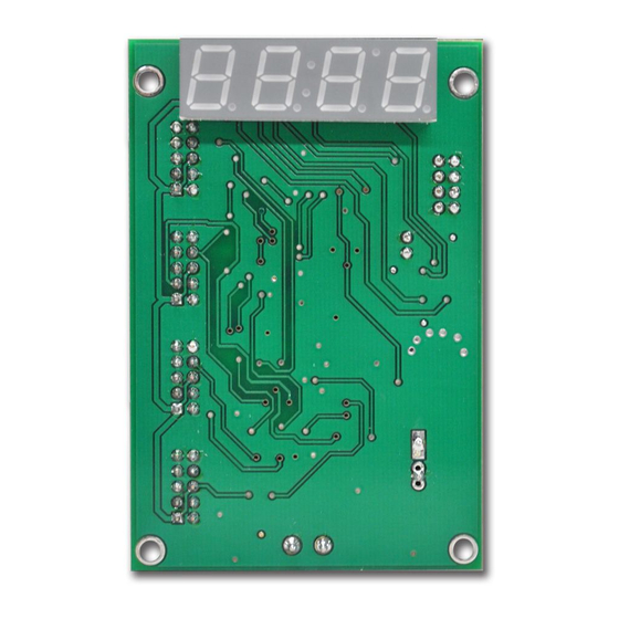
- Page 7 Sensor 1 Test jumper Pin 1 Option Sensor 2 Jumpers Pin 1 Sensor 3 Pin 1 Sensor 4 Pin 1 Power Connector 6v-18v AC or DC Input polarity does not matter Figure 1...
-
Page 8: Operation
Operation When power is applied to the TrainSpeed unit, it will display the jumper settings for a short time by displaying oP.x where ‘x’ is the jumper setting shown in table 3. oP.1 After about 2 seconds, if all is connected correctly, the display will show 4.3.2.1 indicating that all sensors have been detected correctly. - Page 9 The unit will work correctly for the sensors listed in this display, so you may test the overall functionality of the TrainSpeed 4 if you want to before troubleshooting a bad sensor. As a test, try tripping the sensors with your finger exactly 1 second apart.
-
Page 10: Error Messages
Error messages There are three error messages that can be displayed during normal operation. If you get a display of Er.F it means that the train was moving faster then 999 mph. Er.F The message Er.S indicates that the train was moving slower then 1 mph. - Page 11 If your layout is powered up by one switch that powers the lights as well as the TrainSpeed 4 power source, you may get missing sensor errors. The unit in this case should operate normally even though the missing sensor error occurred.
- Page 12 Apply power to the unit. You should see the jumper option message ‘oP.x’. Then you will see one of the following displays: L.y.L => both sensors are working correctly H.y.H => both sensors are either disconnected or ‘in the dark’ H.y.L or L.y.H =>...
- Page 13 (power down the unit before swapping cables). If the other set of sensors work, then the problem lies with the sensor cable, not the TrainSpeed 4 display unit. Dismount the sensor pair and inspect the connections between the cable and the optic, and the cable and the connector.
- Page 14 Extension cables can be made from normal male and female ten pin ribbon cable connectors and cable. An extension can be purchased from TCS Inc. or you can buy the parts from Digikey (www.digikey.com). Please note that Digikey has a $25.00 minimum order (or else they will charge you an extra...
- Page 15 wire to the pin 1 indications on the connectors. Also make sure that the cable is ‘square’ to the connector. Wall transformers Radio Shack AC adaptors NTE 57-9D-600-4 or NTE 57-9D- 600-2 will work with this unit. Cut the circular connector off that comes with the adapter, strip and tin the wires, and connect them directly into the screw terminal power connectors on the TrainSpeed display unit.
- Page 16 TCS Inc. 215-453-9145 Main Number 215-257-0735 Tech Number www.tcsdcc.com...
Need help?
Do you have a question about the TrainSpeed 4 and is the answer not in the manual?
Questions and answers