Table of Contents
Advertisement
Quick Links
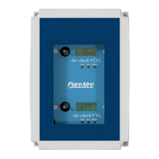
PureAire Dual Oxygen & Carbon Dioxide
Monitor
Instruction Manual
Part Number 99188
Oxygen Range 0-25%
Carbon Dioxide Range 0-50,000ppm
PureAire Monitoring Systems, Inc.
1140 Ensell Road
Lake Zurich, Illinois 60047
Phone:847-726-6000
Fax:847-726-6051
Toll-Free:888-788-8050
pureairemonitoring.com
Rev. 1 September 2022
Advertisement
Table of Contents

Related Manuals for PureAire 99188


Summary of Contents for PureAire 99188
- Page 1 PureAire Dual Oxygen & Carbon Dioxide Monitor Instruction Manual Part Number 99188 Oxygen Range 0-25% Carbon Dioxide Range 0-50,000ppm PureAire Monitoring Systems, Inc. 1140 Ensell Road Lake Zurich, Illinois 60047 Phone:847-726-6000 Fax:847-726-6051 Toll-Free:888-788-8050 pureairemonitoring.com Rev. 1 September 2022...
- Page 2 Our goal is to provide the best after-sale service and support in the industry. That is just one way PureAire takes that extra step to ensure your complete satisfaction.
- Page 3 PureAire Monitoring Systems Please Read Before Installation The following will damage the Oxygen/Carbon Dioxide Monitors. The Oxygen and Carbon Dioxide Monitors require 24 VDC regulated power. Please Do Not connect the monitors to any voltage that exceeds 24 Volts DC, or ANY AC Voltage.
-
Page 4: Table Of Contents
3.7.3.1. Recommended Maintenance Schedule ...... 14 3.7.4. Loss of Power Indicator .......... 14 3.7.5. Alarm Reset ............14 3.8. PureAire Oxygen Monitor Programming ..... 15 3.8.1. Joystick Operation ..........15 3.8.2. Program Flowchart ..........16 3.8.3. Entering the Password ......... 20 3.8.3.1. - Page 5 PureAire Monitoring Systems 3.10.1. Sensor Verification..........39 3.10.1.1. Sensor Verification Gas ....... 39 3.10.1.2. Sensor Verification Equipment ....39 3.10.2. Sensor Verification Procedure ......40 3.10.2.1. Sensor Verification to Nitrogen ....41 3.10.2.2. Sensor Verification to Oxygen..... 41 4: Carbon Dioxide Monitor Specifications ..............43 4.1 Performance Specifications ..........
-
Page 6: 1:Introduction
Unlike electrochemical sensor cells, the zirconium oxygen sensor cell and patented NDIR carbon dioxide cell provide stable readings even in areas where temperature and humidity levels are changing. PureAire’s Dual O Monitor is suitable for either indoor or outdoor use. -
Page 7: Key Features
10 years of continuous operation. Unlike concentration O cells, PureAire’s exclusive zirconium oxide sensor cell does not need an oxygen reference gas for proper operation. The O monitor can detect low oxygen levels in confined spaces and process tools without the need for a reference gas. -
Page 8: 2:Installation
2.2. Mounting Enclosure The PureAire monitor is designed primarily for wall mounting and should be installed at a height convenient for operation, maintenance, and viewing of the instrument display. The following is a drawing of the mounting dimensions. The monitor should be installed in a location where gas leaks are likely to occur or where released gases may accumulate. -
Page 9: Component Identification
1. Digital Display — Backlit display for showing the oxygen levels in percent. 2. Joystick — Used for selecting and adjusting the built-in menus. The PureAire O monitor is available with optional dual-level user selectable relays. The joystick is also used to select alarm levels, relay settings, and reset any latching visual and audio alarms. -
Page 10: Front View Exterior With Relays
PureAire Monitoring Systems 2.3.1. Front View Exterior with Relays Alarm Indicators — Three LED indicators for showing: 1. Alarm level 1 Orange LED 2. Alarm level 2 Red LED 3. Fault Alarm Yellow LED... -
Page 11: Monitor Interior
PureAire Monitoring Systems 2.3.2. Monitor Interior 1. Power Analog Terminal Block — This terminal block is where the 24VDCpower and 4-20 mA analog output connection is made. 2. Oxygen Sensor Connector — This connector is where the Oxygen sensor cell is connected. -
Page 12: Sample Inlet Filter
PureAire Monitoring Systems 2.4. Sample Inlet Filter To protect the pump from water, a special filter is supplied with the monitor. On installation, attach the water filter to the sample inlet by pushing the filter into the ¼” tube compression fitting. - Page 13 PureAire Monitoring Systems Photo shown is a waterproof monitor located at the risk site. If any length of sample tube is needed to sample remote, the water filter must be located at the end of the sample tubing. ¼” tube push to...
-
Page 14: 3:Oxygen Monitor Specifications
Loss of VDC power (analog signal drops to 0 mA). Sensor cell failure: Fault relay activated. Operating Temp: -40° to 134°F (-40° to +55°C); consult PureAire for lower or higher operating temperatures. Humidity: 0 to 95% RH; consult PureAire for sensors that can operate in100% condensing RH environments. -
Page 15: Oxygen Monitor System Default Factory Settings
PureAire Monitoring Systems 3.4. Oxygen Monitor Default Factory Settings The PureAire O Deficiency Monitor is shipped with factory defaults for the alarm relay settings. The following are the factory defaults: Menu Function Factory Default Menu Defined Set 4-20mA loop The mA output is set at... -
Page 16: Wiring
PureAire Monitoring Systems 3.5. Wiring PureAire monitors require a 3-wire shielded cable for analog output and 24 VDC power input. A three-wire shielded cable; 3-conductor, 18 AWG-stranded General Cable E2203S.30.860, or equivalent is recommended for the connection. The analog out and VDC power in connections are made on the terminal block inside the monitor housing. -
Page 17: Initial Startup
The instrument should now be powered up. Upon power up, the PureAire O Monitor LCD displays the PureAire logo and then starts a 4-minute, (240 seconds) count down as the current to the zirconium oxide O sensor stabilizes. The monitor will output a 4 mA signal during the entire warm- up period. -
Page 18: Normal Operation
In the event of a system fault, a specific factory-defined code will be displayed on the local digital display. This code will indicate the exact nature of the system fault. CAUTION DO NOT connect to a powered current loop receiver. The PureAire Oxygen monitor supplies the current loop power. Instrument Faults 3.7.2. -
Page 19: Routine Maintenance Schedule
See Section 3.9.10 for how to make minor adjustments. Loss of Power Indicator 3.7.4. In the event the PureAire O monitor loses 24VDC power, the 4-20 mA analog output signal drops to 0mA. The LCD display will also display a blank screen. Alarm Reset 3.7.5. -
Page 20: Pureaire Oxygen Monitor Programming
Pushing the joystick down again will stop the scrolling and display the gas again. NOTE: The PureAire O Deficiency Monitor will continuously monitor oxygen while accessing the menus. The alarm, fault relays, and mA output are all active and on line while making any changes to the menus. -
Page 21: Program Flowchart
PureAire Monitoring Systems Program Flowchart 3.8.2. ENTER OXYGEN PASSCODE PASSWORD 20.9% PASSCODE SET 4mA SET 4-20mA ZERO LOOP SET 20mA SPAN FORCE LOOP AVAILABLE FORMAT NORMAL FORMATS RELAY 1 INVERT FORMAT NORMAL RELAY 2 INVERT FORMAT FAULT NORMAL RELAY INVERT... - Page 22 PureAire Monitoring Systems SET ALARM PASSCODE SET ALARM 1 NORMAL THRESHOLD POLARITY POLARITY INVERT SET ALARM 2 NORMAL POLARITY INVERT SET AUDIO ALARM NORMAL POLARITY INVERT AUTO LATCHING NONLATCH LATCHING RELAY 1 LATCH LATCHING NONLATCH RELAY 2 LATCH LATCHING NONLATCH...
- Page 23 PureAire Monitoring Systems *NOTE: ZERO SUPPRESSION FUNCTION IS NOT ZERO PASSCODE OKAY 000* AVAILABLE FOR SUPPLRESION OXYGEN SET RELAY 1 SET ALARM 19.5% ALARM THRESHOLDS SET RELAY 2 18.0% ALARM SET AUDIO ALARM 19.5% SET ALARM 1 SET ALARM 0.0%...
- Page 24 PureAire Monitoring Systems MANAGE ENTER NEW PASSCODE OK ENTER MINIMUM PASSWORD PASSWORDS OF 2 CHARACTERS ENABLE USER ENABLED PASSWORD DISABLED RESET TO RESET USER FACTORY PASSWORD DEFAULT...
-
Page 25: Entering The Password
PureAire Monitoring Systems Entering the Password 3.8.3. The PureAire Oxygen monitor is supplied with a factory set password to prevent unauthorized access The Password is 557. to the menus. The following explains how to enter the password. Push the joystick once to the right. Enter Password will scroll on the first line of the digital display. -
Page 26: Changing User Password
PureAire Monitoring Systems Changing the User Password 3.8.3.1. The PureAire Oxygen monitor is supplied with a factory set password to prevent unauthorized access to the menus. The user can change this password and the following explains how to change the password. - Page 27 PureAire Monitoring Systems Push the joystick again to the right to select the third entry. Push the joystick up or down to select the third and final digit. The character being entered will flash and the first and second characters entered will remain lit. You are now ready to enter the 3-digit password.
- Page 28 Push the joystick in, (like a doorbell) to reset the password back to 557. Push the joystick left 4 times to go back to the measuring mode. NOTE: If you lose your password Oxygen please contact PureAire with your 20.9% serial number or DTM number...
- Page 29 ..Set 4mA zero… 20.9% This is the menu at which to adjust the 4mA output being sent from the PureAire O Monitor. To change this value, push the joystick right to display the 4 mA setting. The display will indicate a value between 0 and 255 counts.
- Page 30 PureAire Monitoring Systems This is the menu at which to adjust the 20mA output being sent from the PureAire O Monitor. To change this value, push the joystick right to display the 20mA span setting. The display will indicate a value between 0 and 255 counts. Pushing the joystick up increases the value and pushing the joystick down decreases the value.
- Page 31 ..Format Relay 1… 20.9% This is the menu at which to adjust the first level alarm relay state on the PureAire Monitor. To change this value, push the joystick right to display the relay state. The display will Indicate INVERT.
- Page 32 … Format Relay 2.. 20.9% This is the menu at which to adjust the second level alarm relay state on the PureAire Monitor. To change this value, push the joystick right to display the relay state. The display will Indicate INVERT.
- Page 33 PureAire Monitoring Systems This is the menu at which to adjust the fault alarm relay state on the PureAire Monitor. To change this value, push the joystick right to display the relay state. The display will Indicate INVERT. Pushing the joystick down will change the relay state from INVERT to NORMAL.
- Page 34 Push the joystick down to access the next sub-menu; Set Audio Alarm Polarity will scroll on the display. This is the menu at which to adjust the second level alarm polarity state on the PureAire O Monitor. ..Set Audio Alarm Polarity...
- Page 35 PureAire Monitoring Systems NOTE: The built-in horn is designed to operate in only one alarm mode. It will activate in either a decreasing alarm or an increasing alarm mode only. The horn activation is immediate any time an alarm threshold is exceeded.
- Page 36 ..Set Latching Relay 1… 20.9% This is the menu at which to adjust the first level alarm relay state on the PureAire Monitor. To change this value, push the joystick right to display the relay state. The display will Indicate LATCH.
- Page 37 Set Latching Audio Alarm. ..Set Latching Audio Alarm… 20.9% This is the menu at which to adjust the Audio alarm relay state on the PureAire Monitor. NOTE: The O system must have the audio alarm option module installed to access this menu.
- Page 38 PureAire Monitoring Systems After entering the fault relay state, the display will default back to the Set Latching menu. The display will indicate the following: ..Set Latching.… 20.9% 3.9.5. Resetting a Latching Alarm To reset a latching alarm relay, you must enter the password correctly and then push the joystick down to enter the reset command.
- Page 39 Although the menu permits the changing of settings, it is disabled in the Oxygen monitor. The factory default is set at 000. NOTE: This function is not available on the PureAire Oxygen monitor. …Zero Suppression…...
- Page 40 PureAire Monitoring Systems This is the gas concentration at which the instrument’s second-level alarm will be activated. To change the displayed value, push the joystick to the right to display the second-level alarm setting. The display will indicate a value between 00.0% and 25.5%.
- Page 41 3.9.9. Set Alarm Hysteresis PureAire’s oxygen monitor may be used as a control system. When used to regulate oxygen levels the need of a dead band, “hysteresis” may be required for the alarm relays. This menu will permit the setting of the alarm hysteresis to a desired concentration of Oxygen.
- Page 42 0 and 255 counts. Pushing the joystick up increases the counts and decreases the percent oxygen value displayed on the PureAire. Pushing the joystick down decreases the counts and increases the oxygen value displayed on the PureAire. As the counts increase and decrease the percent oxygen displayed will also increase and decrease.
- Page 43 Press the joystick to the left to revert to the Sensor Adjustment menu. NOTE: The “Set Module Zero” menu is not available for the Oxygen monitor. This menu was designed for PureAire toxic and corrosive gas monitors. When selected, nothing will happen. Push the joystick Left to leave this menu.
- Page 44 NOTE: If the instrument is connected to a controller, set the controller to the standby mode to avoid accidental alarms. NOTE: If your safety protocol requires, you may subject the PureAire monitor to different concentrations of oxygen span gas. *Air Liquide can be reached at 800-638-1197...
- Page 45 0 and 255 counts. Pushing the joystick up increases the counts and decreases the percent oxygen value displayed on the PureAire. Pushing the joystick down decreases the counts and increases the oxygen value displayed on the PureAire. As the counts increase and decrease the percent oxygen displayed will also increase and...
- Page 46 Grade air. Turn off the regulator and remove the Zero grade air from the monitor. The final reading should be within ± 0.3% of the span gas concentration. To see the exact span gas concentration the entire PureAire O monitor needs to be...
- Page 47 NOTE: For best results, the Oxygen monitor should be protected from wind and high airflow when gas calibrating with test gas. NOTE: To see a true zero, the entire PureAire O monitor needs to be completely immersed in a zero-oxygen environment.
- Page 48 Loss of VDC power (analog signal drops to 0 mA). Sensor cell failure: Fault relay activated. (Must have Alarm relay option for cell failure to operate) Operating Temp: 32° to 122°F (0° to +50°C); consult PureAire for lower or higher operating temperatures. Humidity: 0 to 95% RH.
- Page 49 PureAire Monitoring Systems System Default Factory Settings 4.4. The CO Monitor is shipped with factory defaults for the alarm relay settings. The following are the factory defaults: Menu Function Factory Default Menu Defined Set 4-20mA loop The mA output is set at the...
- Page 50 The instrument should now be powered up. Upon power up, the CO monitor LCD displays the PureAire logo and then displays CO on the top line and the actual PPM reading on the bottom line. The monitor will also output the proper mA signal to remote devices:...
- Page 51 Fault code F01 NOTE: All system faults are displayed on the front panel. Each fault has its ‘own specific code to identify the specific problem. Please contact PureAire whenever a fault is displayed. NOTE: When using your own power supply please ensure that the voltage is regulated to 24VDC +/- 0.5 volts.
- Page 52 PureAire Monitoring Systems, Inc. Items to check Check for power and proper operation Condition/status The unit should be outputting approximately 4.6 when operating mA signal when the carbon dioxide is at properly ambient 400ppm. The LCD digital display should also indicate approximately 405 ppm level when the carbon dioxide level is at ambient.
- Page 53 PureAire Monitoring Systems, Inc. 4.8. Carbon Dioxide Programming The CO monitor is supplied with user-selectable settings to adjust the alarm settings, 4 and 20mA output, and minor sensor adjustments. The settings are arranged in menus that are accessed by moving the joystick. To access the menus a factory set password is used.
- Page 54 PureAire Monitoring Systems, Inc. Program Flowchart 4.8.2.
- Page 55 PureAire Monitoring Systems, Inc.
- Page 56 PureAire Monitoring Systems, Inc.
- Page 57 PureAire Monitoring Systems, Inc.
- Page 58 PureAire Monitoring Systems, Inc. 4.8.3. Entering the Password The CO PureAire monitor is supplied with a factory set password to prevent unauthorized access to The Password is 557 the menus. The following explains how to enter the password. Push the joystick once to the right. Enter Password will scroll on the first line of the digital display.
- Page 59 4.8.3.1. Changing the User Password The CO PureAire monitor is supplied with a factory set password to prevent unauthorized access to the menus. The user can change this password and the following explains how to change the password. Push the joystick down to access the Manage Passwords Menu. Manage Passwords will scroll on the first line of the digital display.
- Page 60 PureAire Monitoring Systems, Inc. Push the joystick again to the right to select the third entry. Push the joystick up or down to select the third and final digit. The character being entered will flash and the first and second characters entered will remain lit.
-
Page 61: Enable User Password
PureAire Monitoring Systems, Inc. NOTE: If on the second entry the password entered was different from the first, the display will take you back to the “Re-enter Password Screen”. You will need to repeat steps 2 through 11. If you do not enter the password correctly, the monitor remembers the last password that was properly input. -
Page 62: Entering The Menus
PLC controller or SCADA system. You can also connect the CO monitor to a DC ammeter to read the mA output. Please consult PureAire for more information. From this main menu, pushing the joystick to the right will select the sub-menu and the digital display will scroll the following: ..Set 4mA zero…... -
Page 63: Set Formats
PureAire Monitoring Systems, Inc..Set 20mA Span… Push the joystick down to access the next sub-menu; Set 20mA Span will scroll. This is the menu at which to adjust the 20mA output being sent from the CO Monitor. To change this value, push the joystick right to display the 20mA span setting. The display will indicate a value between 0 and 255 counts. - Page 64 PureAire Monitoring Systems, Inc. NORMAL INVERT NOTE: When the CO relay state is changed to INVERT, the Orange alarm LED will illuminate. After entering the relay state push the joystick left to enter the setting. The display will scroll the following: ..Format Relay 1 CO2…...
- Page 65 PureAire Monitoring Systems, Inc. To change this value, push the joystick right to display the relay state. The display will indicate NORMAL. This is the factory default state for the fault relay. Pushing the joystick down will change the relay state from NORMAL to INVERT.
-
Page 66: Set Alarm Threshold Polarity
PureAire Monitoring Systems, Inc. 4.9.3. Set Alarm Threshold Polarity Alarm Threshold Polarity determines if an alarm concentration is set above or below a threshold value. For example, if an alarm of 19.0% for oxygen is selected, the Alarm Threshold Polarity must be set to Invert for the monitor's alarm to activate when the reading goes below 19.0%. -
Page 67: Set Latching
PureAire Monitoring Systems, Inc. To change this value, push the joystick right to display the relay state. The display will Indicate INVERT. Pushing the joystick down will change the relay state from INVERT to NORMAL. INVERT NORMAL NOTE: When the CO relay state is changed to NORMAL, the internal horn will sound... - Page 68 PureAire Monitoring Systems, Inc. This is the menu at which to adjust the CO alarm relay state on the CO Monitor. To change this value, push the joystick right to display the relay state. The display will Indicate NONLATCH. Pushing the joystick down will change the relay state from NONLATCHING to LATCHING.
-
Page 69: Resetting A Latching Alarm
PureAire Monitoring Systems, Inc. Push the joystick down to access the next sub-menu; Set Latching-Audio Alarm will scroll on the display. This is the menu at which to adjust the Audio alarm relay state on the CO Monitor. ..Set Latching-Audio Alarm.. -
Page 70: Set Zero Suppression
PureAire Monitoring Systems, Inc. You can select from 0 seconds up to 255 seconds after an alarm level has been exceeded before the alarm relays to activate. To change this value, push the joystick right to display the time screen. The display will indicate a value between 0 and 255 seconds. - Page 71 PureAire Monitoring Systems, Inc. This is the gas concentration at which the CO level must be displaying to activate the alarm. To change the displayed value, push the joystick to the right to display the CO level alarm setting. The display will indicate a value between 0 ppm and 50,000 ppm.
-
Page 72: Set Alarm Hysteresis
PureAire Monitoring Systems, Inc. 4.9.9. Set Alarm Hysteresis PureAire’s CO monitor may be used as a control system. When used to regulate carbon dioxide levels the need of a dead band, “hysteresis” may be required for the alarm relays. This menu will permit the setting of the alarm hysteresis to the desired concentration of Carbon Dioxide. - Page 73 PureAire Monitoring Systems, Inc. Push the joystick down to access the next sub-menu; Set Alarm 2, CO , Hysteresis. on the digital display. ..Set Alarm 2, CO2, Hysteresis… It will display a value 00 PPM, (factory default). Pushing the joystick up increases the PPM up to a maximum value of 1000 PPM.
- Page 74 PureAire Monitoring Systems, Inc. To access the Auto Calibration mode, go to the Sensor Adjustment main menu. ..Sensor Adjustment.. Press the joystick right to access the Set CO sensor span sub-menu. ..Set CO2 sensor span.. Push the joystick down to access the Turn CO autocal on the menu.
-
Page 75: Main Operation Mode
PureAire Monitoring Systems, Inc. To turn OFF this feature push the joystick right. The display will scroll the following: ..Press ENTER to continue.. Push the joystick in, (like a doorbell) to activate the autocal feature. Push the joystick in, (like a doorbell) to activate the autocal feature. The CO alarm horn will activate momentarily. - Page 76 Only qualified personnel should perform maintenance and sensor verification Sensor Calibration, CO 4.10.1. PureAire incorporates the use of an NDIR (Non-Dispersive Infrared) CO sensor in the CO Monitor. The sensor is factory calibrated and will always provide an accurate reading that is the difference between a baseline setting and the actual CO measurement.
- Page 77 PureAire Monitoring Systems, Inc. To adjust the baseline setting, expose the monitor to ambient air, either outside or in a well-ventilated room for about 5 minutes. OR expose the sensor to a span gas cylinder with a certified concentration of CO...
- Page 78 PureAire Monitoring Systems, Inc. Push the joystick in, (like a doorbell) to set the reading to 400PPM. You have now reset the CO sensor to 400PPM. To exit the calibration menu, push the joystick left four times to display the...
- Page 79 PureAire Monitoring Systems, Inc. 5: Appendix How to connect a remote fan contactor to the O monitor...
- Page 80 PureAire Monitoring Systems, Inc. How to convert 4-20mA current output to a 1-5 VDC voltage output PureAire O2 Monitor User PLC input 4-20mA output Attach 250-ohm resistor to the PLC or device input...
Need help?
Do you have a question about the 99188 and is the answer not in the manual?
Questions and answers