Table of Contents
Advertisement
Quick Links
Advertisement
Table of Contents

Related Manuals for PureAire Air Check O2


Summary of Contents for PureAire Air Check O2
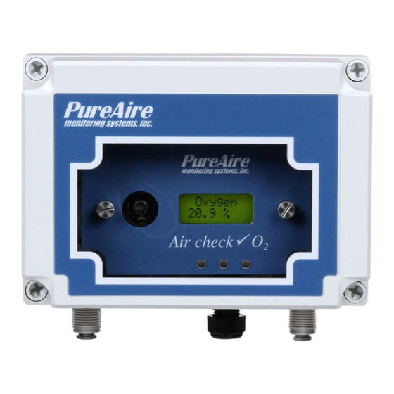
- Page 1 ✓ Air Check Water Resistant O Monitor Instruction Manual Part number 99118 PureAire Monitoring Systems, Inc. 1140 Ensell Road Lake Zurich, Illinois 60047 Phone: 847-726-6000 Fax: 847-726-6051 Toll-Free: 888-788-8050 pureairemonitoring.com...
- Page 2 Our goal is to provide the best after sale service and support in the industry. That is just one way PureAire takes that extra step to ensure your complete satisfaction. Thank you again for investing in PureAire Monitoring Systems for your monitoring needs and I’m proud to welcome you to our family of valued and satisfied customers.
- Page 3 Please Read Before Installation The following will damage the Air Check Oxygen monitor. 1. The Air Check O monitor requires 24 VDC regulated power. Please Do Not connect the monitor to any voltage that exceeds 24 Volts DC, or ANY AC Voltage. 2.
-
Page 4: Table Of Contents
PureAire Monitoring Systems, Inc. Table of Contents 1: Introduction ........................2 1.1 Key Features ................ 2 1.2 Component identification ............ 3 2: Specifications ........................7 2.1 Performance Specifications ..........7 2.2 Gas Detection System ............7 2.3 Signal Outputs ..............7 2.4 Electrical Requirements ............ -
Page 5: 1: Introduction
Each system consists of a long-life zirconium oxide sensor cell and three-wire transmitter. The Air Check ✓O monitor may be used as a stand-alone gas detector, linked to optional PureAire single and multipoint controllers, or connected to your own centralized control and surveillance system. This manual covers the installation, operation, and maintenance of the Air Check ✓water resistant O... -
Page 6: Component Identification
PureAire Monitoring Systems, Inc. 1.1.3 Calibration The Air Check ✓O monitor incorporates a stable zirconium oxide sensor that rarely requires adjustment. Changing barometric pressure changes or changes in temperature and humidity do not affect the zirconium oxide oxygen cell. The earth is a wonderful source of calibrated oxygen at 20.9%, therefore under ambient conditions, visual verification of the Air Check ✓O... - Page 7 PureAire Monitoring Systems, Inc. Sample Exhaust — This permits the flow of oxygen to exit the enclosure. Cable strain relief — This is the sealed opening in the transmitter housing for connecting the input power, 4-20 mA output and relay wiring.
- Page 8 PureAire Monitoring Systems, Inc. water resistant monitor front cover removed Alarm and Fault Relays & Terminal blocks Relays Flow Sensor Sensor connector Sample pump connector Sample Pump 1.2.3 Transmitter Interior 2. Sensor cell connector 1. Power Analog output Terminal Block...
- Page 9 PureAire Monitoring Systems, Inc. Power Analog Terminal Block — This terminal block is where the 24VDC power and 4-20 mA analog output connection is made. Sensor Cell Connector — This connector is where the Oxygen sensor cell is connected. NOTE: Never connect the oxygen sensor to this connector while the monitor is powered.
-
Page 10: 2: Specifications
Loss of VDC power (analog signal drops to 0 mA). Sensor cell failure: Fault relay activated Operating Temp: -40° to 104°F (-40° to +40°C); consult PureAire for lower or higher temperature Humidity: 0 to 100% RH; IP65 water resistant enclosure Environment: Altitude 2000 m, PSU only UL spec. -
Page 11: System Default Factory Settings
PureAire Monitoring Systems, Inc. 2.6 AirCheck O System Default Factory settings The Air Check ✓O water resistant monitor is shipped with factory defaults for the alarm relay settings. The following are the factory defaults: Menu Function Factory Default Menu Defined... -
Page 12: 3: Installation
If possible, avoid areas with high temperatures. ✓ WARNING: The Air Check monitor is not designed for installation in hazardous areas. Consult PureAire for information on enclosures for use in hazardous environments. 3.2 Mounting 3.2.1 Transmitter Enclosure The Air Check ✓O... - Page 13 PureAire Monitoring Systems, Inc. 3.2.3 Enclosure Mounting Feet Mounting Feet Can be oriented in any direction Feet can also be removed for mounting the O monitor flush with a wall or other surface 10 | P a g e...
- Page 14 PureAire Monitoring Systems, Inc. 3.2.4 Air Check ✓ Sample Inlet Filter To protect the pump from dust and water, the use of a special filter is supplied. On installation, attach the particulate/water filter to the sample inlet by pushing the filter into the ¼” tube compression fitting.
- Page 15 PureAire Monitoring Systems, Inc. Photo shown is a waterproof monitor located at the risk site. If any length of sample tube is needed to sample remote, the water filter must be located at the end of the sample tubing. ¼” tube push to...
-
Page 16: Wiring
The instrument should now be powered up. Upon power up, the Air Check ✓ O monitor LCD displays the PureAire logo and then starts a 4-minute, (240 second) count down as the current to the zirconium oxide O sensor stabilizes. The monitor will output a 4 mA signal during the entire warm- up period. - Page 17 The pump flow is set at the factory and should not require adjustment. It has a range to accommodate tubing lengths of 3 feet to over 100 feet. If flow adjustment is necessary, please contact PureAire. NOTE: Normal flow rate is 0.25 liters per minute. (250cc/min)
-
Page 18: 4: Normal Operation
EEPROM Fault 08 NOTE: All system faults are displayed on the front panel. Each fault has it’own specific code to identify the specific problem. Please contact PureAire whenever a fault is displayed. ** When using your own power supply please ensure that the voltage is regulated to 24VDC +/- 0.5 volts. -
Page 19: Routine Maintenance Schedule
PureAire Monitoring Systems, Inc. NOTE: If a Fault condition clears itself, (Yellow LED is no longer illuminated) The Fault message will continue to scroll until manually cleared. To clear the fault message, push the joystick down (- Minus) 4.3 Routine Maintenance Schedule Continuous gas detection systems depended upon to measure and detect hazardous gas leaks in the workplace requires periodic maintenance to ensure proper operation. - Page 20 PureAire Monitoring Systems, Inc. Joystick – You must enter the password to enter the reset function. After the password is entered and accepted, push the joystick in; (enter) to reset the alarms. Remote Reset – Refer to section 1.2.4. for location on PC board. The alarm relay board has a two-pin connector for wiring to a remote switch.
-
Page 21: 5: Air Check O Monitor Programming
PureAire Monitoring Systems, Inc. 5: Air Check ✓O Monitor Programming The Air Check ✓O Deficiency Monitor is supplied with user selectable settings to adjust the alarm settings, 4 and 20mA output and minor sensor adjustments. The settings are arranged in menus that are accessed by moving the joystick. -
Page 22: Program Flowchart
PureAire Monitoring Systems, Inc. 5.2 Program Flowchart Oxygen Enter PassCode OK 20.9% Password Set 4mA Set 4-20mA PassCode OK loop Zero Set 20mA Span NOTE: All numerical values shown are only examples and are not Factory Defaults Not available Force loop... - Page 23 PureAire Monitoring Systems, Inc. Set Alarm Set Alarm 1 Normal Threshold Polarity PassCode OK Polarity Invert Set Alarm 2 Normal Polarity Invert Set Audio Not available Alarm Polarity Set Latching Set Latching Nonlatch Relay 1 NOTE: All numerical Latch values...
- Page 24 PureAire Monitoring Systems, Inc. NOTE: Zero suppression function is not Zero PassCode OK available for Suppressio 000 * Oxygen Set Alarm Set Relay 1 19.5% Thresholds Alarm Set Relay 2 18.0% Alarm Set Audio 19.5% Alarm NOTE: All Set Alarm Set Alarm 1 0.0%...
- Page 25 PureAire Monitoring Systems, Inc. Enter New Manage PassCode OK User Passwords Password Enable User Enabled Password Disabled Reset User Not Available Password 22 | P a g e...
-
Page 26: Entering The Password
PureAire Monitoring Systems, Inc. 5.3 Entering the Password The Air Check Oxygen monitor is supplied with a factory set password to prevent unauthorized access The Password is 557. to the menus. The following explains how to enter the password. 1. Push the joystick once to the right. Enter Password will scroll on the first line of the digital display. -
Page 27: Changing The User Password
PureAire Monitoring Systems, Inc. 5.4 Changing the User Password The Air Check Oxygen monitor is supplied with a factory set password to prevent unauthorized access to the menus. The user can change this password and the following explains how to change the password. - Page 28 PureAire Monitoring Systems, Inc. 6. Push the joystick again to the right to select the third entry. Push the joystick up or down to select the third and final digit. The character being entered will flash and the first and second characters entered will remain lit.
- Page 29 If you misplace or loose your password, contact PureAire with the monitors DTM# for instructions on recovering your password. The DTM# is displayed by moving the joystick to the left.
-
Page 30: Entering The Menus
PLC controller or SCADA system. You can also connect the Air Check O monitor to a voltmeter to read the mA output. Please consult PureAire for more information. From this main menu, pushing the joystick to the right will select the sub menu and the digital display will scroll the following: ..Set 4mA zero…... - Page 31 NOTE: The Force Loop function is not available on the Air Check O monitor. It was designed for toxic and corrosive gases. This is the sub menu is only used on PureAire’s toxic and corrosive monitors. …Not Available.. 20.9% Push the joystick to the left brings you back to the pervious menu. The digital display Will scroll the following: ...Force Loop…..
-
Page 32: Set Formats
PureAire Monitoring Systems, Inc. 5.5.2 Set Formats This is the menu at which to adjust the relay states for the two gas alarm relays and the individual instrument fault relay. NOTE: The O system must have the relay module installed to access this menu. If no relay module is installed the display will indicate N/A, (not available) Push the joystick down to access the next main menu, Set Formats. - Page 33 PureAire Monitoring Systems, Inc. From this main menu, pushing the joystick to the right will select the sub menu and the digital display will scroll the following: ..Format Relay 1… 20.9% Push the joystick down to access the next main menu, Set Formats. The display will scroll the following: …...
-
Page 34: Set Alarm Threshold Polarity
PureAire Monitoring Systems, Inc. ..Format Fault Relay... 20.9% This is the menu at which to adjust the fault alarm relay state on the Air Check Monitor. To change this value, push the joystick right to display the relay state. The display will Indicate INVERT. - Page 35 PureAire Monitoring Systems, Inc. To change this value, push the joystick right to display the relay state. The display will Indicate INVERT. Pushing the joystick down will change the relay state from INVERT to NORMAL. Press ENTER to accept the value.
-
Page 36: Set Latching
PureAire Monitoring Systems, Inc. ..Set Audio Alarm Polarity... 20.9% NOTE: The O system must have the audio alarm option module installed to access this menu. If this option is installed the display will indicate N/A, (not available) NOTE: The optional built-in horn is designed to operate in only one alarm mode. - Page 37 PureAire Monitoring Systems, Inc. NOTE: The O system must have the relay module installed to access this menu. If no relay module is installed the display will indicate N/A, (not available) .Set Latching… 20.9% This menu will permit the setting of the two alarm relays and the fault relay settings from a latching to a non latching state when they are activated.
- Page 38 PureAire Monitoring Systems, Inc. Push the joystick down to select the next relay to be adjusted. The display will scroll the following, Set Latching Relay 2. ..Set Latching Relay 2… 20.9% This is the menu at which to adjust the second level alarm relay state on the Air Check Monitor.
-
Page 39: Resetting A Latching Alarm
PureAire Monitoring Systems, Inc. NOTE: The O system must have the audio alarm option module installed to access this menu. If this option is installed the display will indicate N/A, (not available) To change this value, push the joystick right to display the relay state. The display will Indicate LATCHING. -
Page 40: Set Zero Suppression
PureAire Monitoring Systems, Inc. 20.9% After entering the alarm delay, the display will default back to the Alarm Delay menu and the display will scroll the following: …Alarm Delay… 20.9% NOTE: The alarm delay is only available for alarms 1 and 2. There is no delay for the fault relay. - Page 41 PureAire Monitoring Systems, Inc. Pushing the joystick up increases the value and pushing the joystick down decreases the value. Press ENTER to accept the value. 19.5% 20.9% After entering the relay state, the display will default back to the Set Relay 1 Alarm Threshold Menu.
-
Page 42: Set Alarm Hysteresis
20.9% 5.5.9 Set Alarm Hysteresis PureAire’s oxygen monitor may be used as a control system. When used to regulate oxygen levels the need of a dead band, “hysterisis” may be required. This menu will permit the setting of the alarm hysterisis to a desired concentration of Oxygen. When using hysteresis, the alarm set point now becomes an average alarm setting for an action to occur. -
Page 43: Set Sensor Adjust
PureAire Monitoring Systems, Inc. Press ENTER to accept this value. The digital display will revert back to Set Alarm 1 Hysteresis. ..Set Alarm 1 Hysteresis… 20.9% Push the joystick down to access the next sub menu; Set Alarm 2 Hysterisis will scroll on the digital display. -
Page 44: Main Operation Mode
Press the joystick to the left to revert to the Sensor Adjustment menu. NOTE: The “Set Module Zero” menu is not available for the Oxygen monitor This menu was designed for PureAire toxic and corrosive gas monitors. When selected, nothing will happen. Push the joystick Left to leave this menu. -
Page 45: 6: Maintenance & Cell Verification
20.9%. 6.1.1 Sensor Verification Gas For testing the Air Check ✓ O monitor, PureAire recommends the use of nitrogen. This can be purchased from your gas supplier or from the gas supplier listed below. -
Page 46: Sensor Verification Procedure
PureAire Monitoring Systems, Inc. 6.2 Sensor Verification Procedure CAUTION: Be sure to observe all safety guidelines when generating and using nitrogen. ✓ Under ambient non-oxygen deficient environments, Air Check monitor will indicate a display reading of 20.9%. As the sensor ages, the reading may decrease in value. - Page 47 …Sensor adjustment.. 20.9% 6.2.1 Sensor Verification to Nitrogen PureAire recommends challenging the O monitor with nitrogen every 6 to 12 months. The monitors dust filter has a ¼” male tube fitting designed for connecting sample tubing from a Nitrogen cylinder. Expose the O cell to N using the On-Demand regulator.
- Page 48 PureAire Monitoring Systems, Inc. 6.2.2 Sensor Verification to a known concentration of Oxygen When testing the O monitor to a known concentration of oxygen, the sensor inlet has as a ¼” compression tube fitting designed for connecting the sample tubing. You can connect ¼”...
-
Page 49: 7: Appendix
(Part number 99091) The Remote Display Alarm Indicator is designed to display remote oxygen concentration information from PureAire’ oxygen monitors. All PureAire O monitors have a built in 4-20mA output. The remote display alarm easily connects to the monitor’s input power and mA output connection. An 18 AWG, three conductor, shielded control and instrumentation cable, Belden 8770 or equivalent, is recommended for the connection. - Page 50 PureAire Monitoring Systems, Inc. How to mount the Remote Display Alarm Indicator 1) Open the two side doors to expose the front panel screws. 2) Loosen the 4 screws to separate the front panel from the case. Mount the case to a wall or other flat surface.
- Page 51 PureAire Monitoring Systems, Inc. How to wire the Remote Display Alarm Indicator Identification of switches and controls 1. Alarm Adjusting Switches – These switches are used select the alarm level to be adjusted. They are factory set at 19.5% for Alarm 1 and 18% for Alarm 2. (Normally set at the factory) 2.
- Page 52 PureAire Monitoring Systems, Inc. your oxygen monitor, pushing these switches will automatically adjust the zero and full scale readings on the Remote Digital Display. 4. Alarm Adjusting Buttons – These buttons are used to increase, (UP) or decrease (DOWN) the alarm settings.
- Page 53 PureAire Monitoring Systems, Inc. How to set the zero and full scale range This will need to be set up in the field to adjust to the length of cable between the oxygen monitor and the remote display alarm indicator. To perform this in the field, first enter the password on your oxygen monitor and select the “Set 4-20mA loop”...
- Page 54 How to connect a Horn and Strobe to the O2 monitor This drawing shows how to connect a remote Horn and strobe to PureAire’s Oxygen monitor with the Alarm relay #1 set to a Normally Open position. Note: Federal Signal Horn/Strobe or equivalent (24VDC)
- Page 55 PureAire Monitoring Systems, Inc. How to connect a remote fan contactor to the O2 monitor To external voltage source, 24 VAC, 120 VAC or 240 VAC, 3 Externally powered amps max. relay External relay coil. Relay coil voltage Relay 1, or Relay 2...
- Page 56 PureAire Monitoring Systems, Inc. How to convert 4-20mA current output to a 1-5 VDC voltage output PureAire O2 Monitor User PLC input 4-20mA output Attach 250-ohm resistor to the PLC or device input 53 | P a g e...
Need help?
Do you have a question about the Air Check O2 and is the answer not in the manual?
Questions and answers