Table of Contents
Advertisement
Quick Links
Installation Instructions
Collector Kit
Collectors with Screwed Fittings
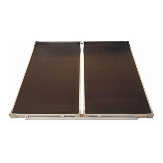
NPT200 SOLAR COLLECTOR
WARNING: Plumber – Be Aware
Use copper pipe ONLY. Plastic pipe MUST NOT be used.
It is a requirement of a solar water heater installation that all
pipe work be in copper and not plastic, due to the effects of
high water temperatures.
This collector kit must be installed and serviced by an authorised person.
Please leave this guide with the householder.
Advertisement
Table of Contents

Related Manuals for Rheem NPT200


Summary of Contents for Rheem NPT200
- Page 1 Installation Instructions Collector Kit Collectors with Screwed Fittings NPT200 SOLAR COLLECTOR WARNING: Plumber – Be Aware Use copper pipe ONLY. Plastic pipe MUST NOT be used. It is a requirement of a solar water heater installation that all pipe work be in copper and not plastic, due to the effects of high water temperatures.
- Page 2 WARNING: Plumber – Be Aware The solar hot and solar cold pipes between the solar storage tank and the solar collectors MUST BE of copper. All compression fittings must use brass or copper olives. The full length of the solar hot and solar cold pipes MUST BE insulated. The insulation must: ...
-
Page 3: Table Of Contents
CONTENTS HOUSEHOLDER - This installation instruction booklet is intended for the installer but you may find it of interest. Components And Kit Contents ..........4 Installation – Solar Storage Tank ..........5 System Installation ..............5 Solar Collector Location ............. 6 Roof Assembly Of Solar Collectors ......... -
Page 4: Components And Kit Contents
The solar water heater is designed for the solar collectors to be roof mounted and the solar storage tank to be installed at ground or floor level. The collector kit is suitable for: Collector Kit – Screwed Fittings (2 solar collectors) 12105000 NPT200 solar collectors 12105000 Part No Kit Components and Description two collectors... -
Page 5: Installation - Solar Storage Tank
SYSTEM INSTALLATION INDIRECT CLOSED CIRCUIT SYSTEM INSTALLATION The system is suitable for installation with NPT200 solar collectors as part of an indirect closed circuit system installation. An indirect closed circuit system has a collector circuit which is separate from the potable water in the solar storage tank. -
Page 6: Solar Collector Location
SOLAR COLLECTOR LOCATION Consideration must be given to the position of the solar collectors in relation to the solar storage tank. There are limitations on both the maximum length of the solar hot and solar cold pipes and the maximum height between the solar “Solar Storage Tank Location”... - Page 7 SOLAR COLLECTOR LOCATION The installation of these solar collectors on a suitable cyclone frame, subject to the frame‟s design criteria not being exceeded: is suitable for installation in geographic locations within Wind Regions C and D as defined in the Building Code of Australia, Australian / New Zealand Standard AS/NZS 1170.2:2002 and the Australian Standard AS 4055-2006, and ...
- Page 8 SOLAR COLLECTOR LOCATION PIPE LENGTHS The solar hot and solar cold pipes between the solar storage tank and the solar collectors shall: be of DN15 bendable grade or hard drawn copper tube. Annealed or soft copper shall not be used. have a continuous fall from the solar collectors to the solar storage tank of 5°...
- Page 9 SOLAR COLLECTOR LOCATION WARNING: Plumber – Be Aware The solar hot and solar cold pipes between the solar storage tank and the solar collectors MUST BE of copper. All compression fittings must use brass or copper olives. The full length of the solar hot and solar cold pipes MUST BE insulated. The insulation must: ...
- Page 10 “Pressure Testing” on page 12. Upon completion of the installation of the NPT200 solar collectors the packaging material may be removed, whether or not the solar circuit is connected to the solar storage tank and / or the solar water heater is commissioned.
- Page 11 SOLAR COLLECTOR LOCATION Maximum Height to Collectors – Indirect Closed Circuit The solar collectors must be the highest point of the system. The maximum height of the solar installation, from the base of the solar storage tank to the top of the solar collectors, is 7.5 m.
- Page 12 SOLAR COLLECTOR LOCATION Pressure Testing The solar water heater, including the collector circuit and solar collectors, is to be isolated during the testing and commissioning of the heated water reticulation system in a building, in accordance with Clause 11.1 and 11.3 (a) of AS/NZS 3500.4.
-
Page 13: Roof Assembly Of Solar Collectors
Remove only sufficient packaging material to enable the installation of the solar collectors. Upon completion of the installation of the NPT200 solar collectors the packaging material may be removed, whether or not the solar circuit is connected to the solar storage tank and / or the solar water heater is commissioned. - Page 14 ROOF ASSEMBLY OF SOLAR COLLECTORS Numbers in parentheses refer to items in the diagram on page 28 for a two solar collector installation. DO NOT MODIFY THESE PARTS IN ANY WAY Solar Collector Location: Select a suitable position for the solar “Solar Collector Location”...
- Page 15 Hot Sensor ROOF ASSEMBLY OF SOLAR COLLECTORS 20-30mm Connection from horizontal Solar Hot Pipe Connection 10-15mm Solar Cold Pipe from horizontal Connection NOTES: - If the roof material is not even where the Hot Sensor 20-30mm collectors are to be installed, then it may Connection from horizontal be necessary to add 10mm for each collector...
- Page 16 ROOF ASSEMBLY OF SOLAR COLLECTORS Tile Roof: Remove the tiles on the next row above the position of the collector rail (1) to expose the rafters. Ensure the collector rail (1) is at the correct angle from the horizontal. Once in position, fix the collector straps (2) to the rafters, using suitable screws or anchors.
- Page 17 ROOF ASSEMBLY OF SOLAR COLLECTORS Collector Rail (top) – Pitched Roof Installation: Locate the second collector rail (1) against the top end of the solar collectors. Hook two collector straps (2) to each collector rail (1). Refer to Detail G on page 25.
- Page 18 ROOF ASSEMBLY OF SOLAR COLLECTORS 10. End Plug: Fit the end plug (5) to the collector connection opposite the inlet connection and below the outlet of the solar collector array. “End Plug Assembly – Screwed Fittings” Refer to on page 21. 11.
- Page 19 ROOF ASSEMBLY OF SOLAR COLLECTORS 13. Hot Sensor Lead: Insert the sensor probe of the hot sensor lead assembly (9) into the sensor housing (4), ensuring the sensor probe is pushed all the way up to the end of the sensor housing (4). Lock it into position with the locking washer and clip provided.
- Page 20 ROOF ASSEMBLY OF SOLAR COLLECTORS INSTALLATION CHECK LIST Once the installation is complete, it is important to check the following: The outlet side of the collector array is between: 20 – 30 mm (for two solar collectors) higher up the roof than the inlet side of the collector array and that the solar hot outlet is higher than the hot sensor housing.
-
Page 21: Connection Details
CONNECTION DETAILS COUPLING COLLECTOR TO COLLECTOR – SCREWED FITTING Refer to installation diagram on page 28 for position and Detail A on page 23. Seat a washer (6) into each of the collector connections to be joined. Fit a collector union (3) to each collector connection of the first solar collector (17) to receive the second solar collector and screw in the unions by hand until they seat firmly against their washer (6). - Page 22 CONNECTION DETAILS COUPLING COLD AND HOT PIPES TO COLLECTOR – SCREWED FITTING Refer to installation diagram on page 28 for position and Detail D on page 24 Detail E on page 24. Seat a washer (6) into the collector connection. Place the connector (10) into the collector connection and screw in the union by hand until it seats firmly against the washer (6).
- Page 23 CONNECTION DETAILS DETAIL A – COLLECTOR UNION ASSEMBLY – SCREWED FITTING DETAIL B – END PLUG ASSEMBLY – SCREWED FITTING FOR AUSTRALIS SERIES 2 AND TITAN SERIES 2 COLL EMS WITH P/No's, ARE SUPPLIED IN ROOF KITS) ARDS DOMESTIC SOLAR DRAIN BACK GTS DESIGN DETAIL C –...
- Page 24 CONNECTION DETAILS DETAIL D – CONNECTOR ASSEMBLY – SCREWED FITTING (SOLAR HOT CONNECTION TO SOLAR COLLECTOR) DETAIL E – CONNECTOR ASSEMBLY – SCREWED FITTING (SOLAR HOT CONNECTION TO SOLAR COLLECTOR) DETAIL SHEET - FOR AUSTRALIS S (ITEMS WITH P/No's, A DETAIL SHEET - FOR AUSTRALIS SE EDWARDS DOMESTIC S (ITEMS WITH P/No's, A...
- Page 25 CONNECTION DETAILS DETAIL F – CLAMPING COLLECTOR TO COLLECTOR RAIL – BOTTOM DETAIL G – CLAMPING COLLECTOR TO COLLECTOR RAIL – TOP 0 COLLECTORS 0 COLLECTORS LIED IN ROOF KITS) IED IN ROOF KITS) AIN BACK AIN BACK...
-
Page 26: Pipe Work Roughing In Dimensions
PIPE WORK ROUGHING IN DIMENSIONS Refer to the diagrams for roughing in dimensions for pipe work to the solar collectors and to the solar storage tank. Remote Gas Boost and Integrated Boost Solar Storage Tanks (Indirect Closed Circuit) Pipe Work to Solar Hot &... - Page 27 PIPE WORK ROUGHING IN DIMENSIONS Solar Pipe Work Roughing In Dimensions Pipe Work to Solar Collectors 2 Collectors 2260 1875 IMENSIONS...
-
Page 28: Installation - Solar Collectors
INSTALLATION – SOLAR COLLECTORS Note: Although the drawing illustrates the solar cold pipe connecting the bottom left hand corner of the solar collectors, the solar cold pipe may be connected to either the bottom right or the bottom left hand corner of the solar collectors. - Page 29 This page is intentionally blank.
- Page 30 This page is intentionally blank.
-
Page 31: Warranty Note
WARRANTY NOTE The solar water heater and its components are covered by a comprehensive warranty. For full details, refer to the Owners Guide and Installation Instructions supplied with the solar storage tank. The part extracts from the Warranty Condition (5) and Warranty Exclusions (c), (d), (g), (h) and 2 of the water heater Warranty should be noted before commencing the installation of the solar collectors. - Page 32 Revision Date: 2010 June 347547A RHEEM AUSTRALIA PTY LTD - ABN 21 098 823 511 1 Alan Street (PO Box 6) Rydalmere NSW 2116 Australia PATENTS This water heater may be protected by one or more patents or registered designs in the name of Rheem Australia Pty Ltd.
Need help?
Do you have a question about the NPT200 and is the answer not in the manual?
Questions and answers