Table of Contents
Advertisement
Advertisement
Table of Contents

Related Manuals for ROC pH/ORP-5500 Series

Summary of Contents for ROC pH/ORP-5500 Series
- Page 1 USER MANUAL pH / ORP Transmitter / Controller pH / ORP-5500 Series...
- Page 2 Introduction Thanks for choosing pH / ORP – 5500 series pH / ORP Controller. Correct sensor installation and parameter setting would show great performance and advantage of this instrument for your good usage. So please carefully read this manual before installation. This instrument is a precise electrochemical analysis meter, the installation and operation should be performed by technicians with relevant professional knowledge.
-
Page 3: Table Of Contents
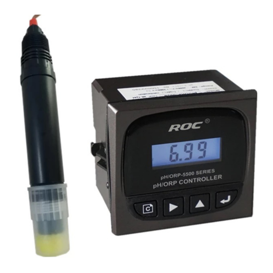
CONTENT 1、CONCEPTION .............. ERROR! BOOKMARK NOT DEFINED. 1.1 WORKING PRINCIPLE ......................5 1.2 APPLICATION ..........................5 1.3 CLASSIFICATION........................5 1.4 TECHNIQUE INDEX ......................... 6 2、INSTALLATION ..........................7 2.1 INSTALLATION OF INSTRUMENT ..................7 2.2 ELECTRICAL CONNECTION ....................8 2.3 DIAGRAM OF 4-20MA OUTPUT ....................10 2.4 RELAY CONTROL CONNECTION .................. - Page 4 Conception pH / ORP-55 00 series is an online pH and ORP Controller , with plug-in PH-1110A sensor, which has good measurement accuracy, anti-interference, easy to install and operational features. FEATURES : White backlight LCD screen, several operations, easy for operation Compatible with six kinds of buffer solutions suitable for international standards.
-
Page 5: Working Principle
1.1 Working Principle A weak voltage change is generated when H affects the inserted sensor, the changeable value will transmit to the instrument. After converting and calculating the generated pH/ORP signal, the instrument will show the values on the screen. 1.2 Application This series of instruments are widely used for online pH/ORP monitoring in environment protection water treatment, pure water treatment, industrial process and so on. -
Page 6: Technique Index
Technical index pH / ORP-5520 Series pH / ORP Online Transmitting Model Controller 0.00~14.00 -2000mV~2000mV Measuremen t Range (0.0~50.0) ℃ Temp. (temperature compensation component: NTC10K) 0.01 pH Resolution 0.1 ºC Temp. 0.1 pH Accuracy ±5 mV(electronic unit) Temp. ±0.5 º C Approximate input impedance 3×10 Ω... -
Page 7: 2、Installation
2. Installation Front view Side view 2.1 Installation of Instrument pH/ORP-5500 series is a panel mounted type instrument, which can be installed easily. -
Page 8: Electrical Connection
Please follow the following steps: 1. Put the instrument into the Panel Cutout 91mm X 91mm (H x W) 2. Then push the quick clamp along with the trench and fasten the instrument. 3. Do not let the instrument drop on the floor when dismounting the meter. Withdraw the quick clamp and take the instrument out carefully Do not place the LCD display screen directly under the sun for the UV could damage the screen. - Page 9 The actual power supply must be the same with marked power supply ! Wiring Connection: INPUT Connect pH/ORP measuring sensor(transparent line) Connect pH/ORP reference sensor(shielded line) Connect the receiving terminal of the Temp. sensor(red) CELL-T Connect grounding terminal of the temp. sensor (black) I+/I- Instrument mode (powered by instrument) T+/T-...
-
Page 10: Diagram Of 4-20Ma Output
2.3 Diagram of 4-20mA output Instrument Mode Transmitting Mode... -
Page 11: Relay Control Connection
Relay Control Connection Relay ON/OFF contact component control wiring diagram Control Mode... -
Page 12: Outline Dimension And Installation Of Sensor
2.6 Outline dimension and installation of the sensor pH/ORP one-piece sensor pH/ORP glass sensor pH/ORP plug-in sensor... -
Page 13: 1Installation Method Of The Sensor
2.6.1 Installation Method of the Sensor Flow Device P34A Flow Device P34B Outlet Inlet pH sensor and temp. sensor by using P33 P16 Submersible Installation... -
Page 14: Installation Requirement
[ Note] : Recommend using the flow device with needle valve (P34) 1. Needle valve flow device (model P34A/B) is recommended when pipeline doing installation. 2. Round sensitive glass type pH probe direct installation in the pipeline, will expose the probe to pressure change, water hammer or siphon effect. -
Page 15: 3、Settings
3. Settings You could set the relative parameter after connecting the instrument and sensor. Please enter into the setting mode to check and set the relative parameters for your first use. These parameters are in different menus. Main Menu Please operate the meter with the keys. Under different modes, the function will be different.: Sign Name Function... - Page 16 1. Set the 0-9 figure under parameter setting status 2. long-press the key under pH measurement status, it will Add key enter into the buffer calibration interface 3. Check mV value under pH measurement status. 1. Enter into the main function menu Enter key 2.
- Page 17 pH / ORP-5500 ◆ Measurement Mode:Normal Display、Transient Display ◆ Setting Mode:Parameter Setting Switch the Mode as Following: Press under pH measurement status check temp. Meas. Mode Meas. Mode No operation for 5 seconds under transient status Normal Display transient display Press under pH measurement status Check mV value...
-
Page 18: Measurement Mode
3.1 Measurement Mode 3.1.1 Normal display The instrument will display the current pH/ORP value after powered on. 3.1.2 Transient display Check the current temp value by pressing under pH measurement status and check current mV value by pressing . The instrument will return to normal display without any operation in five seconds. -
Page 19: Setting Mode
3.2 Setting Mode Some parameters have been set before dispatch. If the test environment changes (such as replacement of electrode, reset of alarm setting etc), please check the parameter which is in different menus. The specific content and operations as follows: 3.2.1 Function selection Choose “pH”... -
Page 20: Temperature Setting
3.2.7 Temperature Setting When “H” or “A” blinks, press “ ” to do the manual temperature compensation (H25.0℃) or automatic temperature compensation (A25.0℃) (automatic temperature compensation need to connect a temp. sensor NTC10K.). Then press save and return to measurement status. his operation is not available for ORP measurement! 3.3 Sensor Calibration 3.3.1 System Calibration... -
Page 21: Buffer Solution Calibration
3.3.2 Buffer Solution Calibration 1. Choose the correct buffer solution to calibrate.; 2. Press the for 3 seconds and enter into buffer solution calibration interface under pH measurement interface, input the current temperature , Press save and enter into buffer solution calibration by pressing 3. -
Page 22: Off-Line Calibration
3.3.3 Off-line Calibration When field calibration is not good to carry on ,the calibration to sensor’s slope by using lab devices and buffer solution is recommended .Take notes of corresponding mV value of buffer solution in room temperature. Input of this record value to off-line calibration is called as manual input calibration. -
Page 23: Maintenance
4. Maintenance 4.1 Sensor Maintenance 1. To avoid long time dry storage, the sensor should be kept in the protection cap with KCl solution -3.0mol/L.; 2. Clean the sensor and calibrate the same on the indicator regularly.; 3. In case of suspended stuff attached, wash it with HCl or NaOH solution in 0.01mol/L and rinse with clean water;... -
Page 24: Instrument And Probe Fault Common Trouble Shooting
4.3 Instrument and probe fault common trouble shooting Problem Possible causes Trouble shooting A. Check to see if there is 24Vvoltage A.Bad connection of No display when between power terminals 24VA and power supply powered on 24VB. B.Instrument fault B. Check by professional technicians. Improper wire connection of sensor A.
Need help?
Do you have a question about the pH/ORP-5500 Series and is the answer not in the manual?
Questions and answers