
Related Manuals for National Instruments NI 9244


Summary of Contents for National Instruments NI 9244
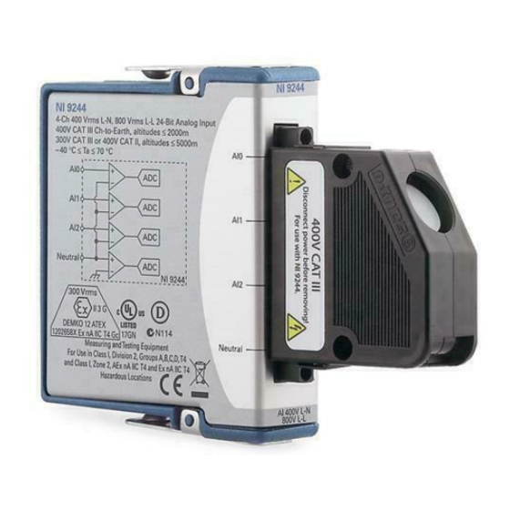
- Page 1 USER MANUAL AND SPECIFICATIONS NI 9244 4-Channel, 400 V L-N, 800 V L-L, 24-Bit Simultaneous Analog Input Module Français Deutsch ni.com/manuals...
-
Page 2: Related Information
This document describes how to use the National Instruments 9244 and includes specifications and pin assignments for the NI 9244. The safety guidelines and specifications in this Note document are specific to the NI 9244. The other components in the system might not meet the same safety ratings and specifications. -
Page 3: Safety Guidelines
You can compromise the safety protection built into the product if the product is damaged in any way. If the product is damaged, return it to National Instruments for repair. NI 9244 User Manual and Specifications | © National Instruments | 3... -
Page 4: Safety Guidelines For Hazardous Voltages
/60 VDC), you must ensure that devices and circuits connected to the module are properly insulated from human contact. You must use the NI 9969 connector backshell kit to ensure that the terminals are not accessible. 4 | ni.com | NI 9244 User Manual and Specifications... - Page 5 Figure 1 shows the NI 9969 connector backshell. Figure 1. NI 9969 Connector Backshell NI 9244 User Manual and Specifications | © National Instruments | 5...
-
Page 6: Safety Guidelines For Hazardous Locations
Safety Guidelines for Hazardous Locations The NI 9244 is suitable for use in Class I, Division 2, Groups A, B, C, D, T4 hazardous locations; Class I, Zone 2, AEx nA IIC T4, and Ex nA IIC T4 hazardous locations; and nonhazardous locations only. -
Page 7: Special Conditions For Hazardous Locations Use In Europe
-40 °C ≤ Ta ≤ 70 °C. If you are using the NI 9244 in Gas Group IIC hazardous locations, you must use the device in an NI chassis that has been evaluated as Ex nC IIC T4, EEx nC IIC T4, Ex nA IIC T4, or Ex nL IIC T4 equipment. -
Page 8: Electromagnetic Compatibility Guidelines
Furthermore, any changes or modifications to the product not expressly approved by National Instruments could void your authority to operate it under your local regulatory rules. 8 | ni.com | NI 9244 User Manual and Specifications... -
Page 9: Special Guidelines For Marine Applications
In addition, take precautions when designing, selecting, and installing measurement probes and cables to ensure that the desired EMC performance is attained. NI 9244 User Manual and Specifications | © National Instruments | 9... - Page 10 Connecting the NI 9244 The NI 9244 provides connections for four analog input channels. Figure 2. NI 9244 Pinout Neutral 10 | ni.com | NI 9244 User Manual and Specifications...
- Page 11 Installing the NI 9969 Using12 AWG to14 AWG Wire Complete the following steps to install the NI 9969 using 12 AWG to 14 AWG wires. NI 9244 User Manual and Specifications | © National Instruments | 11...
- Page 12 Figure 3. 12 AWG to 14 AWG Installation 1 Route wires over the strain-relief piece. 2 Secure strain-relief piece and NI 9969 backshell in place using captive screws. 12 | ni.com | NI 9244 User Manual and Specifications...
- Page 13 Installing the NI 9969 Using16 AWG Wire Complete the following steps to install the NI 9969 using 16 AWG wires. NI 9244 User Manual and Specifications | © National Instruments | 13...
- Page 14 Figure 4. 16 AWG Installation 1 Route wires through the strain-relief pieces. 2 Secure strain-relief piece and NI 9969 backshell in place using captive screws. 14 | ni.com | NI 9244 User Manual and Specifications...
- Page 15 Installing the NI 9969 Using18 AWG to 24 AWG Wire Complete the following steps to install the NI 9969 using 18 AWG to 24 AWG wires. NI 9244 User Manual and Specifications | © National Instruments | 15...
- Page 16 Figure 5. 18 AWG to 24 AWG Installation 1 Route wires over the strain-relief piece. 2 Secure strain-relief piece and NI 9969 backshell in place using captive screws. 16 | ni.com | NI 9244 User Manual and Specifications...
- Page 17 NI 9244. Circuitry Each channel on the NI 9244 provides an independent signal path and ADC. Each terminal has the same input impedance to ground. NI 9244 User Manual and Specifications | © National Instruments | 17...
- Page 18 The NI 9244 returns the voltage between each AI terminal and the Neutral terminal as well as the voltage between the Neutral terminal and the chassis ground. Refer to Figure 6 for a diagram of the equivalent voltages the module returns.
- Page 19 NI recommends using the following phase measurement configurations for typical power distribution networks. Other valid connections are possible if the connections do not exceed the safety rating of the NI 9244. NI 9244 User Manual and Specifications | © National Instruments | 19...
- Page 20 You can connect WYE or delta measurement configurations to the NI 9244. Figure 7. Connecting a 4-Wire WYE Measurement Configuration Phase A Phase B Phase C Neutral Neutral NI 9244 20 | ni.com | NI 9244 User Manual and Specifications...
- Page 21 Figure 8. Connecting a High Leg Delta Measurement Configuration Phase A Phase B Phase C Neutral Neutral NI 9244 NI 9244 User Manual and Specifications | © National Instruments | 21...
- Page 22 Figure 9. Connecting a 3-Wire Delta Measurement Configuration Phase A Phase B Phase C NI 9244 22 | ni.com | NI 9244 User Manual and Specifications...
- Page 23 The 9244 can not measure the entire tolerance Note range or high crest factor signals on 690 V systems in this configuration. Refer to the Specifications section for more information about the input range. NI 9244 User Manual and Specifications | © National Instruments | 23...
- Page 24 Connecting Single-Phase Measurement Configurations You can connect 3-wire or 2-wire single-phase measurement configurations to the NI 9244. Figure 11. Connecting a 3-Wire Measurement Configuration (Split Phase) Neutral NI 9244 24 | ni.com | NI 9244 User Manual and Specifications...
- Page 25 L-L. Phase A to Phase B Voltage = AIO - AI1 where AI0 is the reading from Phase A AI1 is the reading from Phase B NI 9244 User Manual and Specifications | © National Instruments | 25...
- Page 26 Refer to the following equation for an example of converting L-N measurements to L-Earth. Line to Earth = AIx + Neutral where AIx is the analog input channel reading Neutral is the Neutral channel reading 26 | ni.com | NI 9244 User Manual and Specifications...
-
Page 27: Wiring For High-Vibration Applications
Refer to Figure 13 for an illustration of using ferrules. Figure 13. 4-Terminal Detachable Screw-Terminal Connector with Ferrule NI 9244 User Manual and Specifications | © National Instruments | 27... - Page 28 Understanding NI 9244 Filtering The NI 9244 uses a combination of analog and digital filtering to provide an accurate representation of in-band signals while rejecting out-of-band signals. The filters discriminate between signals based on the frequency range, or bandwidth, of the signal.
- Page 29 Therefore, the stopband frequency scales precisely with the data rate. The stopband rejection is the minimum amount of attenuation applied by the filter to all signals with frequencies within the stopband. NI 9244 User Manual and Specifications | © National Instruments | 29...
-
Page 30: Alias-Free Bandwidth
12.8 MHz, but the module also can accept an external master timebase or export its own master timebase. To synchronize the data rate of an NI 9244 with other modules that use master timebases to control sampling, all of the modules must share a single master timebase source. - Page 31 16.667 kS/s, and so on down to 1.613 kS/s, depending on the value of n. When using an external timebase with a frequency other than 12.8 MHz, the NI 9244 has a different set of data rates. The NI 9151 R Series Expansion chassis does not Note support sharing timebases between modules.
-
Page 32: Sleep Mode
Typically, when a system is in sleep mode, you cannot communicate with the modules. In sleep mode, the system consumes minimal power and may dissipate less heat than it does in normal mode. Related Information Power Requirements 32 | ni.com | NI 9244 User Manual and Specifications... -
Page 33: Specifications
) using internal master timebase Minimum........1.613 kS/s Maximum ........50 kS/s Data rate range (f ) using external master timebase Minimum........390.625 S/s Maximum ........51.2 kS/s NI 9244 User Manual and Specifications | © National Instruments | 33... - Page 34 Input impedance, AIx-to-Ground and Neutral-to-GND ......2 MΩ The data rate must remain within the appropriate data rate range. Refer to the Understanding NI 9244 Data Rates section for more information. 34 | ni.com | NI 9244 User Manual and Specifications...
- Page 35 The module returns L-N and N-Earth values only. Refer to Converting L-N Measurements to L-L Converting L-N Measurements to L-Earth sections for details on changing the point of reference of the measurement NI 9244 User Manual and Specifications | © National Instruments | 35...
- Page 36 Phase mismatch (module-to-module, max) ....0.202°/kHz + 360° * f Phase nonlinearity (f = 50 kS/s) 0 kHz to10 kHz ......0.02° max 0 kHz to 20 kHz ......0.06° max 36 | ni.com | NI 9244 User Manual and Specifications...
- Page 37 Typical ......... 0.05% At 1% unbalance Maximum......0.13% Typical........0.05% Zero phase sequence error at 50 Hz and 60 Hz At 5% unbalance Maximum......0.13% Typical ......... 0.05% NI 9244 User Manual and Specifications | © National Instruments | 37...
- Page 38 = 60 Hz)......-78 dB SFDR (1 kHz, -60 dBFS)....-120 dB Total Harmonic Distortion (THD), 1 kHz..........-98 dB 60 kHz..........-100 dB MTBF ..........Contact NI for Bellcore MTBF or MIL-HDBK-217F specifications. 38 | ni.com | NI 9244 User Manual and Specifications...
-
Page 39: Power Requirements
Screw-terminal wiring ...... 0.511 mm diameter (24 AWG) to 2.053 mm diameter (12 AWG) copper conductor wire with 7 mm (0.28 in.) of insulation stripped from the end NI 9244 User Manual and Specifications | © National Instruments | 39... - Page 40 2,001 to 5,000 m altitude Continuous ......400 V Measurement Category II or 300 V Measurement Category III Division 2 and Zone 2 hazardous locations applications Channel-to-earth ground....300 V Measurement Category III 40 | ni.com | NI 9244 User Manual and Specifications...
-
Page 41: Hazardous Locations
Measurement Categories or IV. Hazardous Locations U.S. (UL) .......... Class I, Division 2, Groups A, B, C, D, T4; Class I, Zone 2, AEx nA IIC T4 NI 9244 User Manual and Specifications | © National Instruments | 41... -
Page 42: Safety And Hazardous Locations Standards
UL 60079-0: Ed 5, UL 60079-15: Ed 3 • CSA 60075-0:2011, CSA 60079-15:2012 For UL and other safety certifications, refer to the Note product label or the Online Product Certification section. 42 | ni.com | NI 9244 User Manual and Specifications... -
Page 43: Electromagnetic Compatibility
Class A equipment is intended for use in commercial, light-industrial, and heavy-industrial locations. In Europe, Canada, Australia and New Zealand (per CISPR 11) Class A equipment is intended for use only in heavy-industrial locations. NI 9244 User Manual and Specifications | © National Instruments | 43... -
Page 44: Online Product Certification
To obtain product certifications and the Declaration of Conformity (DoC) for this product, visit , search by ni.com/certification module number or product line, and click the appropriate link in the Certification column. 44 | ni.com | NI 9244 User Manual and Specifications... -
Page 45: Shock And Vibration
Shock and Vibration To meet these specifications, you must panel mount the system. If you are using the NI 9244 with screw terminal, you also must either affix ferrules to the ends of the terminal wires. Operating vibration Random (IEC 60068-2-64)..5 g , 10 Hz to 500 Hz Sinusoidal (IEC 60068-2-6) .. -
Page 46: Environmental Management
This page contains the environmental regulations and directives with which NI complies, as well as other environmental information not included in this document. Refer to the Safety section for more information about altitude. 46 | ni.com | NI 9244 User Manual and Specifications... -
Page 47: Waste Electrical And Electronic Equipment (Weee)
China RoHS compliance, go to ni.com/ environment/rohs_china Calibration You can obtain the calibration certificate and information about calibration services for the NI 9244 at ni.com/calibration Calibration interval ......1 year NI 9244 User Manual and Specifications | © National Instruments | 47... -
Page 48: Worldwide Support And Services
(EMC) and product safety. You can obtain the DoC for your product by visiting . If your product supports calibration, ni.com/certification you can obtain the calibration certificate for your product ni.com/calibration 48 | ni.com | NI 9244 User Manual and Specifications... - Page 49 United States, visit the Worldwide Offices section of to access the branch office ni.com/niglobal websites, which provide up-to-date contact information, support phone numbers, email addresses, and current events. NI 9244 User Manual and Specifications | © National Instruments | 49...
- Page 50 For patents covering National Instruments products/technology, refer to the appropriate location: Help»Patents in your software, the patents.txt file on your media, or the National Instruments Patent Notice at ni.com/patents . You can find information about end-user license agreements (EULAs) and third-party legal notices in the readme file for your NI product.
Need help?
Do you have a question about the NI 9244 and is the answer not in the manual?
Questions and answers