Advertisement
Advertisement
Table of Contents

Related Manuals for Power Flame C1-GO-10


Summary of Contents for Power Flame C1-GO-10
- Page 1 C MANUAL POWER FLAME INCORPORATED...
- Page 2 Power Flame combustion system. Part numbers and component descriptions will match those components supplied. A duplicate set of Burner Specification Sheets is available through Power Flame’s...
- Page 3 It is very important to properly size the oil suction line and oil filter, to provide fuel flow to the burner without exceeding on page 12 (Figure 10). Consult Power Flame Customer 10” suction pressure (vacuum) at the oil pump suction Services Department for sizing assistance regarding port.
- Page 4 Rev.304 Figure 10 Oil Line Sizing Suction Capacity in G.P .H. Total Feet of ” O.D. Total Feet of ” O.D. Total Feet of ” O.D. Total Feet of ” O.D. Copper Tube #2 Fuel Oil Copper Tube #2 Fuel Oil Copper Tube #2 Fuel Oil Copper Tube #2 Fuel Oil 6.
- Page 5 Rev.304 Figure 23 Typical Oil Burner with Low-High-Off or Low-High-Low Fuel/Air Control Mode Using Webster 22R Oil Pump 3 Way Oil By Others Unless Specified CAUTION: Valve 10 on Order. All field piped components Pressure Tap 9 Damper Cylinder must be mounted in the proper ** Burners with Remote Pressure location and proper direction of Atomizing Oil Pumps require a...
- Page 6 Rev.304 to the Webster 22R system. For additional information on your Note 2 specific system refer to the oil piping diagram and the oil pump Component operational sequencing will vary with the specific manufacturer’s bulletin supplied with the burner. Flame Safeguard Control being used. Refer to the specific Flame Safeguard Control bulletin supplied with the burner for complete information.
- Page 7 Rev.304 firing positions and that there is no binding of the Linkage or Note 1 Component operational sequencing will vary with the specific Flame Dampers. Make certain the cast iron Linkage Return Weight Safeguard Control being used. Refer to the specific Flame Safeguard (15) is secure on its Linkage Arm (17).
- Page 8 Rev.304 Figure 26 Gas or Gas/Oil Burner Fuel/Air Premix Adjustment - Gas, Oil or Gas/Oil Burner Diffuser Adjustment Gas/Air Premix Adjustment Knob Blast Tube Diffuser Position Adjustment moving it forward decreases the premix air. Generally, the best (quietest/smoothest) operation is in the full forward position with minimum premix air.
- Page 9 Rev.304 GENERAL START UP PROCEDURES-ALL FUELS All Fuels - General Start Up A thoroughly qualified burner technician should be 3. Tighten all screws on terminal blocks in control cabinet employed to provide the initial burner start up, as well as in case some may have loosened in shipment.
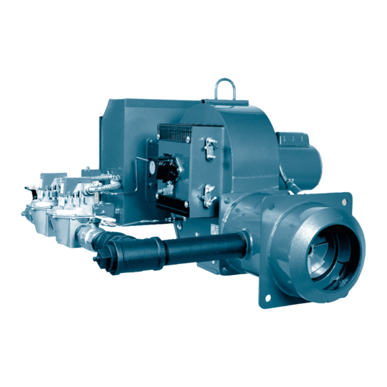
- Page 10 Combination Gas/Oil systems should also refer to page 23, Information on Fuel/Air Modes of Operation for Combination Gas/Oil Units. General Information Power Flame Type C oil burners are of the pressure atom- This may be accomplished by removing cross connect- ing linkage between dampers and locking the unused izing forced draft type, using a single simplex or bypass damper in a fixed position.
- Page 11 (low until the main oil valve is programmed to open. Should fuel/air flow). All Power Flame burners are factory tested a pressure reading be obtained prior to that time, it is and adjusted.
- Page 12 D) With the unit running normally, open the potentiometer or electrically disconnecting the blowdown valve and remove water to the point modulating motor. Power Flame burners are test fired below the low water cutoff setting. The burner at the factory, and linkage adjustments for modulation should turn off and restart automatically when are made at that time.
- Page 13 Rev.709 manufacturer’s bulletin shipped with the burner. It is also 38. Complete the Burner Start Up Information and strongly suggested that all test procedures outlined in the flame Test Data sheets on pages 46 and 47. safeguard control manufacturer’s bulletin be conducted. 7.
- Page 14 Rev.304 HAGO Supply Pressure to Nozzle 300 PSIG at All Rates* Nozzle Size 100 PSIG Approx. High Approx. High Reduced Firing Rates Nominal Fire By-Pass Fire Rate Rating GPH (Return) Approx. Approx. Approx. Approx. Approx. Approx. #2 Fuel Oil Pressure 300 PSIG By-Pass By-Pass...
- Page 15 Rev.304 DELAVAN VARI-FLO 33769 Supply Pressure to Nozzle 300 PSIG at All Rates* Nozzle Size Reduced Firing Rates 100 PSIG Approx. High Approx. High Nominal Fire Rate Fire By-Pass Rating GPH (Return) Approx. Approx. Approx. Approx. Approx. Approx. #2 Fuel Oil 300 PSIG Pressure By-Pass...
-
Page 16: Noisy Pump
19.2 19.8 Oil Nozzle Servicing 1. Nozzles used on Power Flame Type C burners are of two objects to clean nozzles. Damage to orifices or spray types: simplex and internal bypass. The simplex nozzle slots result in off-center or sparky fires. - Page 17 Rev.304 PUMP LEAKS CAPACITY TOO LOW 1. Cover bolts need tightening; gasket broken or 1. Suction lift too high (see page 12, Figure 10) defective 2. Air leak in suction line 2. Mechanical seal (used on certain models) may be 3.
- Page 18 Rev.304 Figure 32 Gas/Oil Burner Firing Head Cutaway View Showing Direct Spark Ignition On Oil, Gas Pilot Main Gas Flame Ignition - Using A Common Scanner For Both Fuels Electrode Support Choke 1 ” Boiler Flange Oil Nozzle Assembly Ignition Elec- trode Blast Tube Stainless...
-
Page 19: Gas Operation
Rev.304 TROUbLE ShOOTING SUGGESTIONS GAS, OIL OR GAS/OIL bURNER GENERAL that ignition is instant and that flame signal 1. Burner Fails to Start readings are stable and above minimum values. A. Defective On/Off or fuel transfer switch. Replace. Use a manometer or 0 to 10” W.C. gas pressure B. -
Page 20: Oil Operation
Rev.304 4. Gas High Fire Input Cannot Be Achieved F. Burner gas train components sized too small for supply pressure. Increase component size as A. Gas company pressure regulator or meter appropriate. operating incorrectly, not allowing required gas G. Automatic gas valve not opening fully due to pressure at burner train inlet. -
Page 21: Maintenance
Rev.304 6. White Smoke Formation on Oil Firing B. Nozzle defective—replace. Nozzle mesh filter dirty—clean or replace. A. Oil/Air ratios incorrect due to excess air, or oil C. Oil supply pressure to nozzle too low. Readjust. flow is too low. Readjust for proper fuel input, CO and smoke reading. -
Page 22: Periodic Check List
Rev.304 PERIODIC ChECk LIST Item Frequency Checked By Remarks Gages, monitors, and indicators Daily Operator Make visual inspection and record readings in log Instrument and equipment Daily Operator Make visual check against heat exchanger settings manufacturer’s recommended specifications Firing rate control Weekly Operator Verify heat exchanger manufacturer’s settings...
Need help?
Do you have a question about the C1-GO-10 and is the answer not in the manual?
Questions and answers