Table of Contents
Advertisement
Quick Links
Advertisement
Table of Contents
Troubleshooting

Subscribe to Our Youtube Channel
Related Manuals for Power Flame Ultra CMax


Summary of Contents for Power Flame Ultra CMax
- Page 2 For use by Qualified Service Personnel Only Rev. 5/2017 Rev. 10/2016 WARNING The improper installation, adjustment, alteration, service or maintenance of this equipment can result in fire, explosion, serious injury, or death. Refer to this manual. For assistance or additional information consult a qualified installer, service agency or the gas supplier.
-
Page 3: Table Of Contents
GENERAL PRODUCT INFORMATION Principle of Operation Unpacking and Handling Warranty and Spare Parts Information General Components Information INSTALLATION Gas Supply Piping Oil Supply Piping Combustion Air Requirements Burner Mounting: General Combustion Chamber: General START UP PROCEDURES Burner Start Up and Service Test Equipment Required General Start-Up All Fuels Fuel Change-Over Procedure Burner Start-Up Sequence Instructions: Gas... -
Page 4: General Product Information
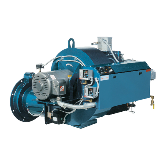
1.1.1 The Power Flame Model UCM Burner is a forced draft, high swirl, partial premix/nozzle mix gas burner which incorporates flue gas recirculation on both gas and oil to achieve ultra low NOx reduction. The combustion air is furnished by an integrally mounted combustion air fan. The Power Flame packaged combustion system can be operated under positive or negative furnace pressures with clean, efficient combustion in a wide range of combustion chamber conditions. -
Page 5: Warranty And Spare Parts Information
L in the right hand column on the sheets. Claims on shortages or damage must be immediately filled with the carrier. 1.3.1 Power Flame offers a 15 month Limited Warranty on all components from the date of shipment (see inside of back cover for details). 1.3.2 The Owners Information envelope packed with the burner contains a Quality Control Questionnaire. -
Page 6: Installation
Figure 1: Gun Assemblies View 2.1.1 The installer should contact the local gas utility for information related to available supply pressures, limitations on allowable pressures in the building, general piping requirements and applicable codes, restrictions and regulations. Considerations of these types, as well as written permits and other state, city and local codes should be discussed with and approved by the appropriate governing bodies. - Page 7 regarding flow capabilities of a chosen line size, the next largest size is recommended. Use correction factors (multiplier) at right for other specific gravities and pressure drops. 2.1.6 Refer to Figure 2 for the typical gas piping schematic to meet U.L. requirements in the UCM burner firing ranges.
-
Page 8: Oil Supply Piping
Figure 2: Typical Gas Piping Schematic for Model UCM Burner 2.2.1 The UCM burner is designed for use with commercial standard grade No. 2 fuel oil. 2.2.2 It is recommended that prior to installation, NFPA 85 and all other national, state, local and other applicable codes be reviewed to ensure total compliance with their requirements including, but not necessarily limited to, the use of anti-siphon valve(s), oil safety valve(s) (OSV), or other acceptable means to prevent siphoning of the oil when the tank is above burner level. - Page 9 Refer to Figure 4 for fuel pump oil piping connection information. Further information relating to burner oil piping can be found in Table 3. Burner Pump Suction Compressor Flow Model Rate (CFM) @ Capacity (GPH) 145 psi UCM-200 10.8 UCM-250 10.8 UCM-300 10.8...
- Page 10 150 200 300 350 150 200 300 350 Total Length of 1" NPS Pipe Total Length of 1 1/4" NPS Pipe Figure 3: Oil Line Sizing Figure 4: Oil Piping Details...
-
Page 11: Combustion Air Requirements
2.3.1 Fresh air required to support combustion, as well as to provide adequate location ventilation, must be supplied. All types of fuel require approximately 10 cubic feet of standard air (sea level at 60°F) per 1000 BTU’s firing rate, for theoretical perfect combustion. In actual practice, a certain amount of excess air is required to ensure complete combustion, but this can vary substantially with specific job conditions. -
Page 12: Start Up Procedures
3.1.1 The following test equipment is required to ensure proper start up and adjustment of burner equipment to obtain maximum efficiency and reliability of operation. 3.1.2 Equipment required: For any fuel: · analyzer (Required) · NOx analyzer (Required) · Stack thermometer ·... -
Page 13: Fuel Change-Over Procedure
3.2.8 Check breaching and stack to ensure that they are open and unobstructed. 3.2.9 Check blower (and oil pump motor, as applicable) rotation by momentarily making contact of the motor starters. Proper rotation is imprinted on the fan housing and (if supplied) the remote oil pump set assembly. - Page 14 3.3.7 It should now be possible to angle the gun assembly toward the access opening and pull the entire assembly out. 3.3.8 Once the gas gun assembly is out verify that the center gas o-ring is still in place, then install the blanking flange and bolts.
-
Page 15: Burner Start-Up Sequence Instructions: Gas
3.4.1 Prior to burner start up – contact the local gas company to determine if any correction factors have to be applied to their indicated meter flow rates. This information is important as it relates to achieving specific heat exchanger BTU/HR inputs. 3.4.2 Refer to the gas piping diagram furnished with the burner. - Page 16 3.4.12 Adjust the burner as necessary to provide smooth ignition of the main flame. If the flame signal drops significantly when the main automatic gas valve opens, slightly increase the pilot gas pressure to attain a stable flame signal value. 3.4.13 Refer to paragraph 3.4.20 and 3.4.21 carefully for recommended limit control and other control devices operational checkout.
-
Page 17: Burner Start-Up Sequence Instructions: Oil
3.4.26 Complete the Burner Start-up Information and Test Data sheets on pages 32, 33 and 34. 3.5.1 Power Flame Model UCM oil burners are of the air atomizing forced draft type. 3.5.2 Check oil and gas piping (if applicable) for leaks and check all controls for compliance with codes and insurance requirements. - Page 18 the pilot regulator does not exceed the regulator or pilot solenoid valve rating. When bleeding air from the pilot line system, do not allow the venting of gas into the room. 3.5.5 Install required system measuring devices: Appropriate flame signal meter to the flame safeguard control Stack thermometer, O and Smoke Test sample line in the breaching Draft gauge to the combustion chamber test point...
- Page 19 ignition timing sequence to stop while air and gas pressure adjustments are being made. See page 25 for details on gas pilot ignition adjustments. 3.5.10 Cycle the burner several times to make certain the pilot is operating reliably. Shut the pilot gas cock and cycle the burner through pre-purge.
-
Page 20: Ifgr: Induced Flue Gas Recirculation
3.5.23 Set and check operation of low Oil Pressure Switch. Set at approximately 80% of low fire oil pressure. Check visually, or test electrically to confirm that circuit opens at the proper oil pressure. 3.5.24 Check Atomizing Air Switch. Set just below the minimum operating pressure during pre-purge. Check visually, or test electrically to confirm that circuit opens on a loss of atomizing air pressure. -
Page 21: Principle Of Operation
The IFGR Low NO adapter is pre-mounted to the UCM burner and IFGR pipe sizing recommendations are included in Figure 7. The IFGR piping is not provided by Power Flame. 4.3.2 Install the IFGR pipe from the stack, or last pass smoke box, to the burner IFGR connecting flange. If the takeoff is from the stack, it should be upstream of any stack damper or barometric damper. -
Page 22: Determining Percentage Of Ifgr
Combustion problems are generally caused by too much IFGR volumetric flow. If stack flue gas pressures are high, typically above +0.1" W.C., a reducing orifice may be required in the IFGR piping to restrict excessive flow. Consult Power Flame if this circumstance is encountered. 4.4.5 Typical IFGR percentages range from 20% to 30% on a sub 9 PPM NO system. - Page 23 % IFGR value across the graph on the Y-Axis. Excess air (% ) in the stack or fuel type have very little effect on the calculated % IFGR. Software for this calculation can be provided by Power Flame through our Customer Service Department (620-421-0480 or CSD@powerflame.com).
-
Page 24: Troubleshooting
Figure 9: combustion efficiency for Natural Gas as function of O and net stack temperature 4.5.7 Most codes and standards regarding NOx emissions are based on a PPM level corrected to 3% O . To correct NOx to a specified O level, use the following formula: ×... -
Page 25: Gas Pilot Ignition Adjustment
Pump not securely mounted Vibration caused by bent shaft or misalignment Pump overloaded Suction line vacuum so high that vapor forms within the liquid 5.1.4 Capacity Too Low Suction lift too high Air leak in suction line Suction line too small Check valve or strainer is obstructed or dirty Mechanical defects –... -
Page 26: Trouble Shooting Suggestions Gas, Oil Or Gas/Oil Burner: General
Install a 0 to 10” W.C. gas pressure gauge or a manometer in the pilot test tee fitting. Plug an appropriate flame signal meter into the flame safeguard control. Disconnect the high tension ignition lead-wire at the ignition transformer secondary terminal. Either hold onto the insulated portion or let the free ignition wire hang loose, so that it is not able to come into contact with the bare ignition terminal on the transformer. -
Page 27: Trouble Shooting Suggestions: Gas
Gas pilot ignition failure. Refer to pilot adjustment section and readjust to make certain that the ignition is instant and that flame signal readings are stable and above minimum values. Use a manometer or 0 to 10” W.C. gas pressure gauge on pilot test tee to make certain that pressure is as recommended. -
Page 28: Trouble Shooting Suggestions: Oil
Gas company pressure regulator or meter operating incorrectly, not allowing required gas pressure at burner train inlet. Have gas company correct. Gas cock upstream of train inlet not fully open. Check and correct. Gas line obstructed. Check and correct. Gas train main and/or leak test cocks not fully open. Check and correct. Gas supply line between gas company regulator and burner inlet too small. - Page 29 5.6.5 Low Oil Flame Is Established and Proven, but Flame Out Occurs in Transition from Low Fire to High Fire. Defective or incorrect size oil nozzle. Replace. High fire oil pressure too low. Readjust. Air dampers set too far open at low fire, which causes flame to blow out in starting to high fire. Readjust dampers.
-
Page 30: Maintenance
6.1.1 Only qualified service technicians should make mechanical or electrical adjustments to the burner and/or associated control equipment. 6.1.2 Preventive maintenance can usually be performed by building maintenance personnel. 6.1.3 Always follow the information provided in the Owner Operating Instructions at the end of this manual. These should be conspicuously posted in the burner room at the time of the initial burner installation and startup. -
Page 31: Periodic Check List
Item Frequency Checked By Remarks Gages, monitors and indicators Daily Operator Make visual inspection and record readings in log Weekly Operator Verify heat exchanger manufacture’s settings Firing rate control Semiannually Service Technician Verify heat exchanger manufacture’s settings Annually Service Technician Check with combustion test Make visual inspection of linkage Flue, vent, stack or outlet damper... -
Page 32: Burner Start Up Information & Test Data
& & The following information shall be recorded for each burner start up Power Flame model No.____________________ Invoice No.___________________ Serial No._________________ Installation Name________________________________________________________________________________ Start Up Contractors Name________________________________________________________________________ Name of Technician Performing Start Up_____________________________________________________________ Phone_______________________________________ Start Up Date_______________________________________ Type of Gas: Natural Gas_____ LP_____ Other _____________________________ Fuel Oil Grade No. ___________... - Page 33 Oil Firing Pilot Train Pilot Inlet Gas Pressure Pilot Flame signal Low Fire Pilot Test Tee High Fire Vacuum Reading High fire pressure at oil pump inlet Low fire Low fire Oil Nozzle Supply Oil Nozzle ByPass pressure pressure High Fire High Fire Low fire Low fire...
- Page 34 Operation Checklist Checked for Proper Operation of: Low water cut off Barometric damper Boiler room combustion air High water cut off and ventilation provisions Flame safeguard control Oil tank vent system checked ignition failure Flame safeguard control All oil lines checked for leaks main flame failure Burner air flow switch All gas lines checked for leaks...
- Page 35 Open the pilot gas cock. POWER FLAME INCORPORATED 3) Set the main power switch and burner panel control switch to the ON position. Wait 30 2001 South 21 St.
- Page 36 NOTES: ___________________________________________________________________ __________________________________________________________________________ __________________________________________________________________________ __________________________________________________________________________ __________________________________________________________________________ __________________________________________________________________________ __________________________________________________________________________ __________________________________________________________________________ __________________________________________________________________________ __________________________________________________________________________ __________________________________________________________________________ __________________________________________________________________________ __________________________________________________________________________ __________________________________________________________________________ __________________________________________________________________________ __________________________________________________________________________ __________________________________________________________________________ __________________________________________________________________________ __________________________________________________________________________ __________________________________________________________________________ __________________________________________________________________________ __________________________________________________________________________ __________________________________________________________________________ __________________________________________________________________________ __________________________________________________________________________...
- Page 37 NOTES: ___________________________________________________________________ __________________________________________________________________________ __________________________________________________________________________ __________________________________________________________________________ __________________________________________________________________________ __________________________________________________________________________ __________________________________________________________________________ __________________________________________________________________________ __________________________________________________________________________ __________________________________________________________________________ __________________________________________________________________________ __________________________________________________________________________ __________________________________________________________________________ __________________________________________________________________________ __________________________________________________________________________ __________________________________________________________________________ __________________________________________________________________________ __________________________________________________________________________ __________________________________________________________________________ __________________________________________________________________________ __________________________________________________________________________ __________________________________________________________________________ __________________________________________________________________________ __________________________________________________________________________ __________________________________________________________________________...
- Page 38 NOTES: ___________________________________________________________________ __________________________________________________________________________ __________________________________________________________________________ __________________________________________________________________________ __________________________________________________________________________ __________________________________________________________________________ __________________________________________________________________________ __________________________________________________________________________ __________________________________________________________________________ __________________________________________________________________________ __________________________________________________________________________ __________________________________________________________________________ __________________________________________________________________________ __________________________________________________________________________ __________________________________________________________________________ __________________________________________________________________________ __________________________________________________________________________ __________________________________________________________________________ __________________________________________________________________________ __________________________________________________________________________ __________________________________________________________________________ __________________________________________________________________________ __________________________________________________________________________ __________________________________________________________________________ __________________________________________________________________________...
- Page 39 Power Flame Incorporated, hereinafter called Equipment, which is repaired or replaced, shall the Seller, of 2001 South 21 Street, Parsons, carry a warranty equal to the unexpired portion Kansas, hereby warrants equipment of the original warranty. The Seller will manufactured by it and bearing its nameplate...
- Page 40 Manual UCM 05/17 Copyright 2009 Power Flame Incorporated Printed in the U.S.A Power Flame ® Power Flame Incorporated 2001 South 21 Street, Parsons, KS 67357 Telephone: 620-421-0480 FAX: 620-421-0948 Product Support: 620-820-8301 Website: http:www.powerflame.com e-mail: CSD@powerflame.com...
Need help?
Do you have a question about the Ultra CMax and is the answer not in the manual?
Questions and answers