
Related Manuals for Telex VEGA C-5110B


Summary of Contents for Telex VEGA C-5110B
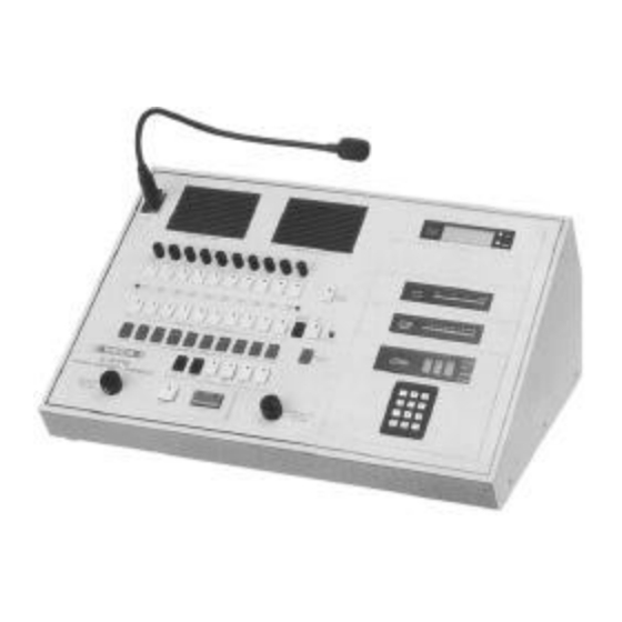
- Page 1 Models C-5110B, C-5111, and C-5112 Ten-Line/Four-Frequency Radio Control Consoles Instruction Manual C-5110B C-5111 C-5112 098-0345A...
-
Page 2: Table Of Contents
Contents Introduction ............2 Operation and Controls. -
Page 3: Introduction
Introduction The Models C-5110B, C-5111, and C-5112 Plug jumpers are provided for simplex 10-line, four-frequency, tone-remote control two-wire operation and for simplex or duplex consoles provide reliable remote control of the four-wire operation. Additionally, jumpers are various functions of two-way radio base provided for proper line termination impedance stations located at up to 10 different sites. -
Page 4: Operation And Controls
Operation and Controls Volume Controls: Independently adjust This action reduces the possibility of accidently speaker level of selected-line audio and interfering with other users on the channel (who unselected-line audio. are using a different CTCSS tone frequency), and is required by FCC Rules. Individual Line Volume Controls ( C-5111 and Adjust... - Page 5 Line Selection: When one of the ten line-select Parallel Single-Line Console Compatibility: switches is momentarily pressed, it latches on The C-5110B, C-5111, and C-5112 consoles are and releases any other latched line switch, compatible with parallel single-line consoles, such as causing the console to switch to the selected the Vega C-510C, which use the industry-standard line.
- Page 6 Figure 3 Upper and Switch PCB Assembly Block Diagram Figure 4 Main PCB Assembly Block Diagram...
-
Page 7: Installation
FIRST CONSOLE ONLY 4 #2 THROUGH N CONSOLES NUMBER P38,P39 RX & TX P38, P39, CONSOLES LOSS 3 P40, P43 P40, P43 TO B 1 TO B 1 TO B 1 0 dB TO A TO B 1 TO B 1 1.5 kΩ... -
Page 8: Disassembly, Setup, And Adjustment
Disassembly, Setup, and Adjustment Verify Function Tones 1. Ground TP6 Make sure that the line cord is unplugged 2. Press F1 and verify 1950 Hz* at 0 dBm before opening. Access to internal controls and 3. Press F2 and verify 1850 Hz* at 0 dBm jumpers is obtained by removing the four 4. - Page 9 Please Note... In the “Upper PC Board Programming and For example, for two-wire-line operation Adjustment” section, “line one” is often you are told to set line one’s P38 and P40 used for examples. The same procedures to “B.” You should also set line two’s P34 and P36 to “B”...
-
Page 10: Upper Pc Board Programming And Adjustment
Upper PC Board Programming and Adjustment The designators given in the following Input Level Adjustments: RX1 (R70) allows programming and adjustment guide refer to adjustment of input sensitivity. This control line “one.” The same procedure, using the should be adjusted to slightly above the individually associated designators, should be threshold of compression with typical voice followed for lines two through ten (for... -
Page 11: Optional Handset Adjustments
Optional Handset Adjustments Earpiece volume level adjusted The console is not designed for a combination EARPIECE LVL control R134. Selected, of duplex operation on some four-wire lines unselected, and sidetone audio is summed into and simplex operation on other two-wire or the handset earpiece. -
Page 12: Notch Tuning And Notch Outphase Control
Notch Tuning and Notch Outphase Control Special Uses for F2, F3, F4 Notch tuning and notch outphasing has been One of the many possible uses for F2, F3, and factory-adjusted and sealed for the best F4 with single-frequency radios is selective 2175-Hz notch. -
Page 13: Special Transmit Audio Levels
Special Transmit Audio Levels Unselected Line 1 to 10 Defeat Assuming that the transmit audio level has been For unused lines and for “lockout” of adjusted to 0 dBm (function-tone and microphone unselected audio on a certain line, move the audio) for a particular line (with the appropriate appropriate jumper plug (P1 to P10) associated line output level control on the upper main PCB... -
Page 14: Group Select
Group Select Timed Mute When group select switch S32 is pressed, the The timed mute switch S11A, when pressed, reset inputs of all ten line-select latches are triggers timer U5A at U5-5 through C4 and pulled low through CR4. When these reset R34. -
Page 15: Debouncer Ics U8, U11, U13, U19
The nine other unselected RX switches S13 Receive audio signal buffered output at U24-7 through S21 operate identically to S12. The RX is applied to the LAM1 (line-activity monitor 1) ALL switch S22 operates flip-flop U20A in the input at U31-13 through C20. At idle, same manner as the other ten switches, but the U31-14,10,8 are high and the line 1 LED Q output at U20-1 connects directly to its LED... -
Page 16: Main Pcb Assembly
When selected line 1 is on, RX audio signal PTT-switch operation causes same from line 1 at U24-7 drives the selected-line sequence of operation as above, except that compressor on the main PCB through U10-9,8, upon function-tone timeout, the crystal RN5, the “E”... -
Page 17: Main Pcb Receive Circuits
Thus, only F3 or F4 programming is enabled Output signal at U25-10 also drives selected RX during function-tone operation. F1 or F2 switch 2175-Hz notch/bandpass filter through U16-8,9. operation generates only the reset pulse, which Bandpass output at U30-8 is amplified and resets U7B, if set, and enables only the F1 or F2 rectified by the U21-8,9,10,12,13,14 circuit. -
Page 18: Main Pcb Transmit Circuits
Main PCB Transmit Circuits Warranty (Limited) During mic-PTT or intercom, the audio signal All Vega signaling products are guaranteed path is from a from a mic input such as the desk against malfunction due to defects in materials mic through C2, U1-2,1, and C50 to the TX and workmanship for three years, beginning at compressor input at U24A-2. -
Page 19: Specifications
Specifications Panel Switch-Selectable Lines: ..10 Tone Frequencies and Accuracies: PTT/Guard, 2175 Hz, 0.01%; MON, 2050 Hz, Each Line Input and Output Impedance 0.1%; F1, 1950 Hz, 0.01%; F2, 1850 Hz, 0.2%; Two-Wire: 600 Ω or 2 kΩ, jumper selectable, F3, 1750 Hz, 0.3%;... -
Page 20: C-5110B Parts List
C-5110B Parts List Part No. Description CKT SYM 010-1105 10-LINE TONE CNSL 011-0091 TOP ASSY C-5110B ....1 098-0344 MAN INST C-5110B ....1 674-0230 CORD AC POWER 3 BLADE . - Page 21 C-5110B Parts List (continued) Part No. Description CKT SYM TOP ASSY 561-0623 SPACER SPCR LED .150....8 ..42 561-0639 SPACER #6 X 3/16 L .
- Page 22 C-5111 Parts List (continued) Part No. Description CKT SYM TOP ASSY 286-1742 CONN AC POWER 3 BLADE ....1 ..21 286-1783 CONN PIN CONTACTS .
- Page 23 C-5110B Parts List Part No. Description CKT SYM 012-0050 PCB ASSY - LOWER 065-0428 PCB C-5110B LOWER ....1 071-0544 SCHEMATIC C-5110B LOWER ....0 102-0120 CAP CER 20P 5% 50V S2L .
- Page 24 C-5110B Parts List (continued) Part No. Description CKT SYM PCB ASSY - LOWER 110-1340 CAP CER .1MF SMALL ....21..C1 110-1345 CAP CER .0022MF 5% NPO .
- Page 25 C-5110B Parts List (continued) Part No. Description CKT SYM PCB ASSY - LOWER 112-1645 CAP ELEC 4.7UF 25V MINI ....5 ..C52 112-1671 CAP ELEC 22 UF 25V 10%RD.
- Page 26 C-5110B Parts List (continued) Part No. Description CKT SYM PCB ASSY - LOWER 133-0001 RES CRBN 1.0 OHM 5% 1/2W....4 ..R41 134-0194 RES RN55D 49.9K 1% 1/4W .
- Page 27 C-5110B Parts List (continued) Part No. Description CKT SYM PCB ASSY - LOWER 136-0032 RES COMP 1K 5% 1/4W....17..R1 R140 136-0035 RES COMP 1.8K 5% 1/4W .
- Page 28 C-5110B Parts List (continued) Part No. Description CKT SYM PCB ASSY - LOWER 136-0048 RES COMP 22K 5% 1/4W ....22..R8 R107 R112 R113...
- Page 29 C-5110B Parts List (continued) Part No. Description CKT SYM PCB ASSY - LOWER 136-0064 RES COMP 470K 5% 1/4W ....1 ..R9 136-0065 RES COMP 560K 5% 1/4W .
- Page 30 C-5110B Parts List (continued) Part No. Description CKT SYM PCB ASSY - LOWER 286-1898 HEADER PWB 34 PIN LO-PROF ... . . 1 ..P6 286-1902 CONN PCB SPACER 8 X 1”...
- Page 31 C-5110B Parts List (continued) Part No. Description CKT SYM 012-0049 PCB ASSY - UPPER 065-0459 PCB 5000 SERIES UPPER ....1 071-0543 SCHEMATIC C-5110B UPPER ....0 110-1340 CAP CER .1MF SMALL .
- Page 32 C-5110B Parts List (continued) Part No. Description CKT SYM PCB ASSY - UPPER 136-0003 RES COMP 8.2 5% 1/4W....10 ..R42 136-0020 RES COMP 100 5% 1/4W .
- Page 33 C-5110B Parts List (continued) Part No. Description CKT SYM PCB ASSY - UPPER 136-0029 RES COMP 560 5% 1/4W ....20..R1 136-0030 RES COMP 680 5% 1/4W .
- Page 34 C-5110B Parts List (continued) Part No. Description CKT SYM PCB ASSY - UPPER 136-0044 RES COMP 10K 5% 1/4W ....1 ..R130 136-0048 RES COMP 22K 5% 1/4W .
-
Page 35: C-5112 Parts List
C-5112 PCB ASSY - VOL/PTT Part No. Description CKT SYM 425-0235 INT CKT UA759 ..... . 11 ..U11 425-0285 IC CMOS 4066 QUAD SW. - Page 36 C-5112 Parts List (continued) Part No. Description CKT SYM PCB ASSY - SWITCH 136-0044 RES COMP 10K 5% 1/4W ....10 ..R16 136-0048 RES COMP 22K 5% 1/4W .
- Page 37 C-5112 Parts List (continued) Part No. Description CKT SYM PCB ASSY - SWITCH 286-1833 TERM QUICK CONNECT ....4 286-1898 HEADER PWB 34 PIN LO-PROF ... . . 1 ..P21 286-1899 HEADER PWB 40 PIN LO-PROF .
- Page 38 C-5112 PCB ASSY - VOL/PTT Part No. Description CKT SYM 012-0049 VOL/PTT ASSY 065-0425 PCB C-5112 VOL/PTT ....1 071-0545 SCHEMATIC C-5112 VOL/PTT ....0 110-1319 CAP CER .01MF SM 50V.
- Page 39 C-5112 PCB ASSY - VOL/PTT (continued) Part No. Description CKT SYM 149-0640 XSTR NPN PN100 T092 SW ....1 ..Q 1 149-0642 XSTR NDMOS 2N7000 TO92 SW .
- Page 40 0710542b_UpG.sch-1 - Wed Jan 16 13:17:24 2002...
- Page 41 0710543c_UpG.sch-1 - Wed Jan 16 13:23:57 2002...
- Page 42 0710543c_UpG.sch-2 - Wed Jan 16 13:30:12 2002...
- Page 43 0710544c_UpG.sch-1 - Wed Jan 16 14:26:19 2002...
- Page 44 0710544c_UpG.sch-2 - Wed Jan 16 14:28:52 2002...
- Page 45 0710545a_UpG.sch-1 - Wed Jan 16 14:30:54 2002...
- Page 46 8601 East Cornhusker Highway, Lincoln, Nebraska, 68507 FEB 2000 Printed in U.S.A. Phone: (402) 467-5321 / (800) 752-7560 Fax: (402) 467-3279 E-mail: vega_signal@earthlink.net, Web: www.vega-signaling.com...
Need help?
Do you have a question about the VEGA C-5110B and is the answer not in the manual?
Questions and answers