
Related Manuals for Telex TDI


Summary of Contents for Telex TDI
- Page 1 Telephone Dispatch Interface Technical Manual Version 2.000 LIT000164000 Rev D 09/2009...
- Page 2 E-mail......TelexDispatchtechsupport@us.bosch.com If the installation site has specially wired alarm equipment connected to the telephone line, ensure the installation of a TDI does not disable your Web ................. www.telex.com alarm equipment. If you have questions about what will disable alarm equipment, consult your telephone company or qualified installer.
-
Page 3: Table Of Contents
Table Contents INTRODUCTION ............................7 General ...................................7 Indicators and Connectors .............................8 ................................8 RONT ANEL Operational Indications ..............................8 Supervisory Indications ..............................8 TDI Reset ..................................8 Telephone Line Monitor ..............................8 ..............................9 ANEL ONNECTIONS Equipment Connection and Setup ........................10 TDI S ..................................10 ETUP IP-223 S ..................................10... - Page 5 FIGURE 3. TDI Rear Connections ........
-
Page 7: Introduction
The TDI (Telephone Dispatch Interface) is a telephone interface device designed to connect the IP-223 Ethernet Adapter Panel to a standard PSTN phone service. The IP-223/TDI combination makes the PSTN phone line a network asset to any Telex IP-based console (i.e., C-Soft, C-6200, IP-1616, or IP-2002) allowing telephone calls to be placed or received at the dispatch position. -
Page 8: Indicators And Connectors
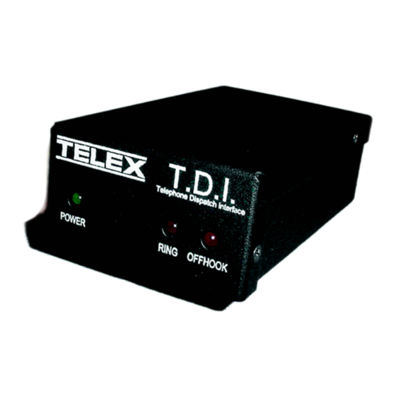
Telephone Line Monitor The TDI continuously monitors the telephone line for faults (i.e., line open or short). When a fault on the line is detected, the RING and OFFHOOK LEDs flash together as long as the telephone line fault exists. When the fault is cleared, the LEDs stop flashing. -
Page 9: Rear Panel Connections
FIGURE 3. Power: Nominal 12VDC 1A max filtered power is applied to the TDI to the 2-pin screw lug connector. The input voltage range is 10-16VDC. Pin 1 is the positive terminal. There is an additional ground lug for chassis ground connections. -
Page 10: Equipment Connection And Setup
Phone: A standard RJ-11 connects the PSTN phone line to the TDI. All telephone signaling and audio is present on the Tip and Ring pair. Description RING Equipment Connection and Setup TDI Setup There are no internal jumpers or adjustments in the TDI enclosure. -
Page 11: Ip-223/Tdi Connections
IP-223/TDI Connections The TDI package includes the interface cable required for connection of the TDI to the IP-223. Connect the interface cable as follows: Plug the Hi-Density male DB-15 connector labeled To TDI into the female Hi-Density DB-15 on the rear of the TDI enclosure. -
Page 13: Installation
CHAPTER 2 Installation IP-223 Web Page Configuration Multicast Address Setup Page To operate with the TDI, the IP-223 must be initially set to Phone mode from the Multicast Address Setup page, as shown in Figure 4. NOTE: • Phone Mode os only available in IP-223 software version 1.08 or higher. -
Page 14: Per Line Setup Window Definitions
Per Line Setup Window Definitions Once the Phone Mode is selected, the TDI operating parameters may be set up from the Per Line Setup web page. The following figures show the general setup for Phone Mode operation. The Serial Port Mode, relays, timeouts, audio levels and various delays are setup here. -
Page 15: Ring Setup
The IP-223 detects and displays the current TDI version. See Figure 7. Serial Port Mode - The TDI operation for the IP-223 may be selected from the drop down menu. Serial Port Param - The IP-223 is automatically configured for communication with the TDI. -
Page 16: Delay Setup
The IP-223 automatically answers the phone after the number of rings entered into this field. Auto Disconnect Time - If the LAM level threshold is not exceeded after the Auto Disconnect time has expired, the IP- 223 will automatically place the TDI Onhook to disconnect the call. NOTE:... -
Page 17: Audio Level Setup
There are no internal jumpers or adjustments inside the TDI enclosure. Advanced circuitry and DSP software algorithms react to changing telephone line impedances resulting in minimal user setup. Each audio input to the TDI (Telco RX and IP-223 TX) is routed through a complex AGC circuit that provides 44dB of dynamic range control. A nominal 0dB input level applied to each of the audio inputs results in ±22dB of dynamic input range control by the TDI. -
Page 18: Save To Eeprom Page
The Line Name is arbitrary and called Line 31 and Line 32 in the case. The RX port numbers need to be unique. Typically they are just the next number in a standard assignment sequence. The Base Radio IP Address is the IP Address of the IP-223 connected to the TDI. -
Page 19: Set Global Parameters
Set Global Parameters Set Global Parameters—Phone Ring Multicast and Port FIGURE 14. Figure 14 shows the Phone Ring Multicast and Port number setting. These values must be the same as shown in Figure 4. C-Soft Phone Control Buttons C-Soft Phone Control Buttons Setup FIGURE 15. -
Page 20: Audio Alignment Procedure
Enter the Receive alignment mode on the IP-223 by pressing and holding the LINE button, then successively pressing and releasing the IC button three (3) times. The TDI must be connected to a live PSTN phone line and then taken offhook. This can be done with C-Soft, or any IP-based Telex Console. -
Page 21: Transmit Audio Alignment
Enter the Tx alignment mode as indicated above. Step 4 From the console, place the TDI in the offhook mode be pressing the offhook button Step 5 From the front panel Tx control, adjust the 1KHz tone level to -12dB on the external meter (ignore the IP-223 display reading). -
Page 22: Tdi Specifications
Red LED = Offhook Rear Panel Connections: • 2-pin power • DB15 • RJ11 Phone Line • Earth Ground Accessories • 19” Rack Mount Kit Telex P/N DSP223RACK (holds up to four (4) TDI boxes) • IP-223 Serial Port Splitter (Telex P/N 30195300)
Need help?
Do you have a question about the TDI and is the answer not in the manual?
Questions and answers