Table of Contents
Advertisement
Quick Links
Headquarters
5th floor,Building 4,Singapore Hangzhou Science Technology Park,No. 6 street,
Hangzhou Economic Development Area,Hangzhou 310018,China
Singapore
2 Venture Drive #11-30 Vision Exchange Singapore
info@supmea.com
www.supmea.com
Supmea Automation Co.,Ltd.
User Manual
Universal controller
U-SUP-DC2000-EN1
Advertisement
Table of Contents

Related Manuals for SUPMEA SUP-DC2000


Summary of Contents for SUPMEA SUP-DC2000
- Page 1 User Manual Universal controller Headquarters 5th floor,Building 4,Singapore Hangzhou Science Technology Park,No. 6 street, Hangzhou Economic Development Area,Hangzhou 310018,China Singapore 2 Venture Drive #11-30 Vision Exchange Singapore info@supmea.com www.supmea.com U-SUP-DC2000-EN1 Supmea Automation Co.,Ltd.
- Page 2 We strive to be correct in the contents of this manual. If you find any errors, please contact us. The contents of this manual are strictly prohibited to be reproduced or copied. This product is forbidden to be used in explosion-proof occasions. Version U-SUP-DC2000-EN1...
- Page 3 Safety Precautions In order to use this product safely, be sure to follow the safety precautions described. About this manual Please submit this manual to the operator for reading. Please read the operation manual carefully before applying the instrument. ...
- Page 4 Do not modify this product.The following safety signs are used in this manual: Hazard, if not taken with appropriate precautions, will result in serious personal injury, product damage or major property damage. Warning:Pay special attention to the important information linked to product ...
- Page 5 immediately, otherwise there will be leakage, electric shock or even a fire accident. Please check the grounding protection status regularly. Do not operate if you think that the protection measures such as grounding protection and fuses are not perfect. Ventilation holes on the product housing must be kept clear to avoid ...
- Page 6 Disclaimer The company does not make any guarantees for the terms outside the scope of this product warranty. This company is not responsible for damage to the instrument or loss of parts or unpredictable damage caused directly or indirectly by improper operation of the user.
-
Page 7: Table Of Contents
Content Chapter 1 Introduction ..................... 1 Chapter 2 Features ....................2 Chapter 3 Parameters ..................... 3 Chapter 4 Fixed installation ..................4 4.1Instrument installation ................. 4 4.2 Instrument wiring ..................6 Chapter 5 key operation ..................9 5.1 Key distribution ...................9 5.2 Button Definition .................. -
Page 8: Chapter 1 Introduction
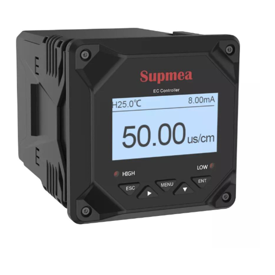
It is used to monitor water quality parameters including pH, ORP, conductivity, dissolved oxygen, turbidity, sludge concentration and other water quality parameters. Through RS485 or current transmission output to the monitoring room for record keeping. www.supmea.com... -
Page 9: Chapter 2 Features
Isolated transmission output is adopted, which is less affected by interference. Using isolated RS485 communication technology. With high and low alarm output function. With sound and light alarm function. With LCD backlight switch control function, improve the adaptability of ambient light. www.supmea.com... -
Page 10: Chapter 3 Parameters
AC250V/3A Distribution output 12V/125mA Relative humidity (10 ~ 85)% (no condensation) Operating temperature (0 ~ 60)℃ AC: (100~240)VAC Input power DC: 24VDC (optional) Temperature: (-15 ~ 65)℃ Storage conditions Relative humidity: (5 ~ 95)% (no condensation) Altitude: <2000m www.supmea.com... -
Page 11: Chapter 4 Fixed Installation
Places where the temperature changes greatly and condensation is easy. Places with a lot of oil smoke, steam, moisture, dust and corrosive gasesInsert the meter into the mounting hole and fasten the butterfly buckle, as shown in Figure 3: www.supmea.com... - Page 12 Chapter 4 Fixed installation Butterfly buckle Front panel Figure 3 Schematic diagram of meter installation www.supmea.com...
-
Page 13: Instrument Wiring
Chapter 4 Fixed installation 4.2 Instrument wiring Figure 4 220VAC wiring diagram www.supmea.com... - Page 14 Chapter 4 Fixed installation Figure 5 24VDC wiring diagram www.supmea.com...
- Page 15 To prevent electric shock, please confirm that the meter is not powered on before connecting the signal cable. To prevent fire, please use double insulated wire. Please do not place live products close to the signal terminals, which may cause malfunction. www.supmea.com...
-
Page 16: Chapter 5 Key Operation
Enter the menu under "Monitoring Interface" Menu Exit menu under "Menu interface" Select the relevant menu under "Menu interface" Downshift Modify the relevant value in the setting state Enter the submenu under "Menu interface" or confirm the Enter modification www.supmea.com... -
Page 17: Chapter 6 Instrument Interface And Operation
Turbidity: optional digital sensor model PTU-8010/PTU-8011 PSS: optional digital sensor model PSS-9011 Dissolved Oxygen: Optional digital sensor model DO-7010/DO-7012/DO-7013/DO-7016 Conductivity: optional digital sensor model TDS-8001 Sensor Type Sensor Type 1. PH/ORP 2. Tubur 3. MLss 4. DO 5. TDS Figure 8 www.supmea.com... -
Page 18: Monitoring Interface
Note: XX automatically switches the measurement parameter type according to the selected sensor. Figure 10 pH monitoring interface Figure 11 ORP monitoring interface www.supmea.com... -
Page 19: Password Verification Interface
After entering the password, use it to enter the main menu interface. The initial password is "0000", you can use the password modification function to modify the password. If you forget your password, please contact our company. User Password Figure 16 www.supmea.com... -
Page 20: Main Menu Interface
Remote setting: Communication Settings, Electrorheological send Alarm setting: parameter setting of high alarm and low alarm. Information inquiry: current version information query. --Main Menu-- 1 .Systeming Setting 2 .Signal Setting 3 .Remote Setting 4 .Alarm Setting 5.Information Inquiry Figure 17 www.supmea.com... -
Page 21: Chapter 7 Configuration Settings
6.86 pH and 9.18 pH respectively (the corresponding values from small to large in USA are 4.01 pH, 7.00 pH and 10.01 pH respectively). After entering the calibration interface, Wait for a while, and after the measured value is stable, use to complete the calibration. www.supmea.com... - Page 22 --Signal Correction-- --Signal Setting-- 1.Online Calibration 2.Signal Correction 3.Measure Param Figure 20 7.2.1.3 Measurement parameters: Select the sensor to measure the primary parameter pH or ORP. --Signal Setting-- --Measure Param-- 1.Online Calibration 1.pH 2.Signal Correction 2.ORP 3.Measure Param Figure 21 www.supmea.com...
- Page 23 After soaking in water, put it in the calibration solution for calibration Figure 22 7.2.2.2 Signal correction: The measured ORP value can be corrected. --Signal Correction-- --Signal Setting-- 1.Online Calibration 2.Signal Correction 3.Measure Param Figure 23 www.supmea.com...
- Page 24 1.Tu Factor 2.Signal Correction 3.Wiping Time Figure 25 7.2.3.3 Wiping Time: Set the sensor wipe time interval (1min, 5min, 15min, 30min, 1h, 4h, 12h, 1d, 3d, 7d). --Wiping Time-- --Signal Setting-- 1.Tu Factor 2.Signal Correction 3.Wiping Time Figure 26 www.supmea.com...
- Page 25 Take the probe out of the first standard solution, rinse with clean water, and dry the sensor. Put the probe into the second-point standard solution, input the standard value of the second-point standard solution, and click. After the measured value data is stable, click to complete the second-point calibration. Figure 27 www.supmea.com...
- Page 26 1.Online Calibration 2.Signal Correction 3.SS Factor Figure 29 7.2.4.4 Wiping Time Set the sensor wipe time interval (1min, 5min, 15min, 30min, 1h, 4h, 12h, 1d, 3d, 7d). --Wiping Time-- --Signal Setting-- 2.Signal Correction 3.SS Factor 4.Wiping Time Figure 30 www.supmea.com...
- Page 27 To calibrate, after entering the calibration interface, you need to wait for a while, and after the measured value is stable, use to complete the calibration. Figure 31 7.2.5.2 Signal Revision The measured dissolved oxygen value can be corrected. --Signal Setting-- --Signal Correction-- 1.Online Calibration 2.Signal Correction 3.Salinity Setting Figure 32 www.supmea.com...
- Page 28 (common standard solutions are 147.0μS/cm, 1413μS/cm and 12.88mS/cm, the actual can be calibrated according to on-site standards ),Press enter the conductivity calibration interface, and then put the connected electrode into the standard solution. After the reading is stable, press the www.supmea.com...
- Page 29 The measured conductivity value can be corrected. --Signal Setting-- --Signal Correction-- 1.Online Calibration 2.Signal Correction 3.Electrode Constant Figure 36 7.2.6.3 Electrode constant: Set the sensor cell constant. --Electrode Constant-- --Signal Setting-- 1.Online Calibration 2.Signal Correction 3.Electrode Constant Figure 37 www.supmea.com...
- Page 30 Set the conversion factor for conductivity and total dissolved solids. --Signal Setting-- --TDS Coefficient-- 3.Electrode Constant 4.Temp Coefficient 5.TDS Coefficient Figure 39 7.2.6.6 Measurement parameters: Select the sensor to measure the main parameter. --Signal Setting-- --Measurement Param-- 4.Temp Coefficient 1.EC 5.TDS Coefficient 2.TDS 6.Measure Param 3.Salinity Figure 40 www.supmea.com...
-
Page 31: Remote Transmission Setting Interface
Jump to 20mA parameter setting, save the setting parameters : : Return to the monitoring interface Return to 4mA parameter setting, return to remote transmission setting : interface Note: The unit xx and the data size are automatically switched according to the selected sensor www.supmea.com... -
Page 32: Alarm Setting Interface
Return to the alarm value parameter setting, return to the alarm setting : interface Note: The unit xx and the data size are automatically switched according to the selected sensor --High Alarm-- --Alarm Setting-- Value 1.High Alarm Hysteresis 2.Low Alarm Figure 43 www.supmea.com... - Page 33 Return to the alarm value parameter setting, return to the alarm setting : interface Note: The unit xx and the data size are automatically switched according to the selected sensor --Low Alarm -- --Alarm Setting-- Value 1.High Alarm Hysteresis 2.Low Alarm Figure 44 www.supmea.com...
-
Page 34: Information Query Interface
Chapter 7 Configuration Settings 7.5 Information query interface Version Information: Query the current software version. --Information Inquiry-- 1.Version Information Figure www.supmea.com... -
Page 35: Chapter 8 Communication Protocol
4 = 57600 Check digit: 0=N81(default),1=O81,2=E8 0x1102 short 0x03/0x06 N: No parity E: Even parity O: odd parity 8: 8 data bits High byte: data version, low byte: device type 0x2000 short 0x03 Data version: 0x01 Device Type: 0x51 www.supmea.com... - Page 36 Measured value 2 is meaningless, value is 0 Measured value 3 is meaningless, value is 0 Measured value 1 is the ORP value, unit: mV 0x0002 Measured value 2 is meaningless, value is 0 Measured value 3 is meaningless, value is 0 www.supmea.com...
- Page 37 Measured value 2 is meaningless, value is 0 Measured value 3 is meaningless, value is 0 Measured value 1 is the sludge concentration value, unit: mg/L PSS/MLSS 0x0008 Measured value 2 is meaningless, value is 0 Measured value 3 is meaningless, value is 0 www.supmea.com...
- Page 38 Function Number of Start address address code registers 0x01 0x03 0x2001 0x0009 0xDFCC Data reply: device address is 0x01 Device Function Return byte Return data address code 0x0001(PH sensor) 0x41C80000(25℃) 0x40E00000(7pH) 0x01 0x03 0x12 0xCDD8 0x00000000(No meaning) 0x00000000(No meaning) www.supmea.com...
-
Page 39: Chapter 9 Failure Analysis And Removal
Question 4: The display area of the screen is that the sensor is not connected? A: Confirm whether the sensor is disconnected. Q5: Wrong sensor selection? A: You can press and hold to re-enter the sensor selection interface and select the correct sensor. www.supmea.com... -
Page 40: Chapter 10 Warranty And After-Sale Service
We promise to deal with the customer's technical questions within 2 hours. For the instruments returned to the factory for maintenance, we promise to issue the test results within 3 working days and the maintenance results within 7 working days after receiving them. www.supmea.com...
Need help?
Do you have a question about the SUP-DC2000 and is the answer not in the manual?
Questions and answers