Table of Contents

Subscribe to Our Youtube Channel
Related Manuals for Selec PID500

Summary of Contents for Selec PID500
- Page 1 PID Temperature Controller PID500 / 110 / 330 OPERATING INSTRUCTIONS Doc. name: OP INST PID500-110-330 OP159-V05/d. Selec Controls Pvt. Ltd., India Tel:91-22-28476443, Fax:91-22-28471733, Website: www.selec.com E- mail: sales@selec.com.
-
Page 2: Table Of Contents
CONTENTS Page no. A) OVERVIEW. 1. Features............... 1 2. Ordering information..........2 B) SPECIFICATIONS............3 C) INSTALLATION. 1. Safety Information..........7 2. Terminal connections........... 9 3. Sensor input wiring..........10 4. Control output wiring..........10 D) PROGRAMMING. 1. Function menu............. 13 2. -
Page 3: Features
Overview 96 x 96 96 x 48 48 x 48 SALIENT FEATURES Universal Input 17 user selectable types including signal inputs. Selectable lower display User selectable lower display options enable quick setting of different parameters such as Set points, Alarms, PID values, Tuning etc. Zone PID 4 programmable control zones. -
Page 4: Ordering Information
0-10V input 0-10V f/b input ORDERING EXAMPLE Note: Input is user selectable. Only Model name & output needs to be specified in the ordering code. PID500 Output 3 ( Relay ) Output 2 ( Relay ) Output 1 ( Voltage ) -
Page 5: B) Specifications
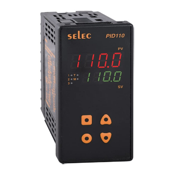
Specifications 1. TECHNICAL SPECIFICATIONS 1. DISPLAY PID500 - 48 X 48 - Dual 4 digit 7- segment LED. Display Upper display : 10mm high Red (process value). Lower display : 7mm high Green (selectable). PID110 - 48x96 - Dual 4 digit 7- segment LED. - Page 6 Specifications 3.2. Alarm Output Relay contact output Rating: 5A @250 VAC or 30 VDC. (Relay 2, Relay 3 (optional) Life expectancy: 100000 cycles at maximum load rating. 3.3. Retransmission output (optional) Current output Range: 0 / 4-20mA. Action: Retransmission Update rate: 100 ms Maximum output load resistance: 500E Voltage output Range: 0-5 / 10V.
- Page 7 Specifications 4.2. Heater current monitor input Single phase, full wave monitoring of load currents Type controlled by main output. 100mA AC output from current transformer. Input 0..999.9A. Display scale range Input resistance 47 ohms. +0.5% of full scale + 1 digit. Accuracy 50...400Hz.
- Page 8 As per BS EN 61326. Panel sealing IP66. 9. WEIGHT : PID500 : 195 gms ; PID110 : 250 gms ; PID330 : 295 gms 10. HOUSING : Flame retardant engineering plastic. 11. INPUT SENSOR RANGES (for 1 C resolution):...
-
Page 9: Safety Information
Installation 1. SAFETY INFORMATION SAFETY SUMMARY This manual is meant for the personnel involved in wiring, installation, operation, and routine maintenance of the equipment. All safety related codifications; symbols and instructions that appear in this operating manual or on the equipment must be strictly followed to ensure the safety of the operating personnel as well as the instrument. - Page 10 Mechanical Installation: For installing the controller 1.Prepare the panel cutout with proper dimensions as shown. OVERALL DIMENSIONS (All dimensions in mm) Panel Cutout PID500 74.5 PID110 PID330 74.5 2.Remove the clamp from the controller. 3.Push the controller into the panel cutout. Secure the controller in its place by pushing the clamp from the rear side.
-
Page 11: Terminal Connections
Installation 2. TERMINAL CONNECTIONS PID500 L (+) (-) N L (+) (-) N TC /RTD1 RS485 TC /RTD1 ANA IP ANA IP TC /RTD2 COM2 TC /RTD2 COM2 ANA IP ANA IP RTD3 RTD3 15 10 15 10 COM1 COM1 COM3 NOTE: Valid for optional configuration. -
Page 12: Sensor Input Wiring
1) Refer input type selection in level 0 of programming menu. 2) For PID500 refer input jumper selection as in point no. 12 on page 6. 3) For 2 wire RTD short terminals 8 & 9 (for PID500) and terminals 3 & 4 (for PID110 & PID330) . - Page 13 Installation Fig2. Output 1 - Relay / SSR to drive contactor(For single phase). PID500 PID110 & 330 230VAC 230VAC Snubber(Optional) Snubber(Optional) SUPPLY SUPPLY (Part No: APRC-01) (Part No: APRC-01) LOAD LOAD Contactor Contactor NOTE: Use snubber as shown above to increase life of internal relay of temperature controller.
- Page 14 1) Configuration is same. 2) Terminal nos - Output 2 : PID500 - 2 - 3. ; PID110 & 330 - 13 - 14 Output 3 : PID500 - 14 - 15. ; PID110 & 330 - 15 - 16...
- Page 16 INPUT PARAMETERS OUTPUT PARAMETERS (main output) AUXILIARY OUTPUT MODES (output 2) *ALARM 2 MODULE (output 3) (optional) SPECIAL FUNCTIONS LOCK MODULE (online parameters) LOCK MODULE (levels) NOTE:- LEVEL 5- Communications Module. LEVEL 9 - Heater current monitor input. LEVEL 10 - Motorised input / Remote set point input. Detailed description of the above levels will be provided as an addendum with the respective models.
-
Page 17: Keys Description
2. KEYS DESCRIPTION Key press Functions together for 3 seconds To enter or exit program mode till Level is displayed. To change levels increase or decrease the level number. key once to view the next / To view function on the same level and previous function. -
Page 18: Level 0-Input Parameters
PROGRAMMING OF LEVELS 3. LEVEL 0 - INPUT PARAMETERS Display Default Display Name & Description Range condition value Input type Select input type as Thermocouples: J,K,T,R,S,C,E, B,N,L,U,W. Platinel II. RTD: PT100 Signal Inputs: Linear mV (-5 to 56mV), Voltage (0 to 10V), Current (4 to 20mA). - Page 19 Display Default Display Name & Description Range condition value Input value Input value scaling point2 Analog input. As per scaling Feed the higher value of the input type point1 to analog input signal. selected. Reverse scaling Analog input. Display scaling points can be reversed.
-
Page 20: Level 1-Output Parameters
DISPLAY 9999 INPUT 0.00mA 20.00mA ISC.L = 0.00 ISC.H = 20.00 DSC.L = 0.0 DSC.H = 9999 RSCL = no 4. LEVEL 1 - OUTPUT PARAMETERS Display Default Display Name & Description Range condition value Set Mode Zone PID = YES in level 4. - Page 21 Display Default Display Name & Description Range condition value % to o/p Output power lower limit PID control power high limit; to o/p for heat power - cool upper limit mode) (in heatcool mode) Output power upper limit PID control O/p power low limit to ON-OFF...
- Page 22 Programming. Display Default Display Name & Description Range condition value Cycle time PID control Cycle time-user Cycle time = USEr Anti-reset windup PID control Anti-reset windup % ARW = MAnL Manual Reset Proportional (for 0.1 band > 0 and resolution) Integral time = 0.
-
Page 23: Level 2-Auxiliary Output Modes
Programming. PARAMETER EXPLANATIONS : ! AUTO TUNING: Auto tuning is a function whereby the controller learns the process characteristics by itself and automatically sets the required P,I and D values. The new P,I,D parameters will be stored in non-volatile memory automatically. TUNE ON is indicated by ‘T’ LED blinking. (For detailed explanations of PID parameters refer USER GUIDE). - Page 24 Programming. Display Default Display Name & Description Range condition value Hysteresis 1. Set2 mode=Fd/rEV/ ALrM (not sensor break); 2. Heat cool mode ( Pb-C=0) Hysteresis bias TC/RTD: 1. Set2 mode=Fd/rEV Analog input: /ALrM (not sensor break); as per decimal 2. Heat-cool point mode (Pb-C=0)
- Page 25 Programming. Display Default Display Name & Description Range condition value For Analog output if Main output = Relay2 NOTE: In HC mode only the following parameter will be prompted :- 1. Set 2 value - this parameter will be prompted as db (dead band) 2.
-
Page 26: Level 3-Alarm 2 Module
Programming 6. LEVEL 3 - ALARM 2 MODULE (OPTIONAL) Display Default Display Name & Description Range condition value Alarm2 mode Alarm 2 should be available. Alarm latch These Hold Alarm parameters are not prompted if Relay status for Alarm1 Alarm 2 mode is OFF. -
Page 27: Level 4-Special Functions
Programming 7. LEVEL 4 - SPECIAL FUNCTIONS Display Default Display Name & Description Range condition value Heat-cool mode The controller can be operated in heat-cool mode if this selection is YES. Zone PID Main Output SSR Output SSR output model Soft start time PID control minutes. - Page 28 Programming Display Default Display Name & Description Range condition value , to Filter time constant seconds , to Output power dampening Analog output seconds model. Rounding increment TC / RTD with TC/RTD resolution = Display as 1 C or Analog per decimal input.
- Page 29 Programming...
-
Page 30: Level 5-Communication Parameters
Programming 8. LEVEL 5 - COMMUNICATION PARAMETERS (OPTIONAL) Display Default Display Name & Description Range condition value Baud Rate Communication station No. Parity Stop bit CONNECTION DIAGRAM Master RS232C CONVERTER Terminating resistor (100 ohm, ½ watt) RS485 RS485 RS485 SLAVE 1 SLAVE 2 SLAVE 32 RS485-RS232 Converter... -
Page 31: Level 6-Lockout Module
Programming 8. LEVEL 6 - PROGRAMMABLE PARAMETER LOCKOUT MODULE Display Default Range Display Name & Description condition value User ID Program access settings # # If LOCK selection is ONL, the following parameters will be prompted. Display Default Display Name & Description Range condition value... - Page 32 Programming...
- Page 33 Programming ONLINE DISPLAY OPTION This function allows user to view online display options. NOTE: The parameters shown below are not prompted if they are locked in level 6. DISPLAY DESCRIPTION DISPLAY CONDITION Set point 1 Online access for Set 2 not valid if Auxillary output = Set point 2 Sensor Break / OFF /...
- Page 34 Programming DISPLAY DESCRIPTION DISPLAY CONDITION This parameter is read only and Output percentage cannot be altered. Note: This parameter is prompted only if Ramp is ON / Elapsed soak time Hold. This parameter is read only and cannot be altered. Note: This parameter is not prompted for 0-10 V / 4-20mA.
-
Page 35: E) User Guide
User Guide USER GUIDE AUTO TUNING: PID - time proportioning Auto tuning is a function whereby the controller with auto reset & rate learns the process characteristics by itself and automatically sets the required P,I and D values. The auto-tuning function can be activated at any Temp. - Page 36 User Guide ! PROPORTIONAL BAND: Proportional band is the area around the set point where the controller is actually controlling the process; the output is at some level other than 100% or 0%. Proportional band is expressed in terms of degree centigrade. If the proportional band is too narrow an oscillation around the setpoint will result.
- Page 37 User Guide DERIVATIVE APPROACH CONTROL: Derivative approach control (DAC) helps in reducing overshoot at startup. The control output cutoff point is derived as DAC x Proportional band. Note that the DAC value is automatically calculated and fed after autotuning (if tuning is initiated at startup). AUTO-TUNE OF HEAT/COOL SYSTEMS: During Autotune of heat/cool systems, the controller switches the cooling output (O2) ON and OFF in addition to the heat output (O1).
- Page 38 User Guide ! ALARM MODES: 1. Absolute alarms (Independent Alarm) : Absolute alarm is a self-existent alarm independent of the main set point.For eg. If the main set point is 100 C and absolute alarm is set as 110 C, the alarm will be activated at 110 C.
- Page 39 User Guide Zone PID: There are 4 control Zones each having a set point and associated P, I and D values which can be programmed as per the process requirements. A control Zone is selected automatically and implemented as per the set value programmed, to accommodate changing process requirements.
-
Page 40: F) Configuration Record Sheet
Configuration Record Sheet Enter the value or selection for each prompt on this sheet so you will have a record of how your controller was configured. Factory Value or Function Prompt Levels Setting Selection Input Parametrs As per input type selected. - Page 41 Configuration Record Sheet Factory Value or Function Prompt Levels Setting Selection Output Parametrs Zone Settings...
- Page 42 Configuration Record Sheet Factory Value or Function Prompt Levels Setting Selection Auxiliary Output Modes Alarm 2 Module...
- Page 43 Configuration Record Sheet Factory Value or Function Prompt Levels Setting Selection Special Function Communication...
-
Page 44: G) Calibration Certificate
Calibration Certificate Model No: PID500-110-330 Claimed Accuracy: ± 0.25% of full scale ±1 digit (After 20min warmup time) Standard used for calibration of the product is traceable to NABL The calibration of this unit has been verified at the following values:...
Need help?
Do you have a question about the PID500 and is the answer not in the manual?
Questions and answers