Table of Contents
Advertisement
BendPak
INCORPORATED
OPERATION AND SERVICE MANUAL
Models
:
1000-BL
1302-BL ("Blue Bullet")
1000-BAS
1302-BAS
1000-BA
1302-BA
1502-BL
1502-BAS
1502-BA
SHIPPING DAMAGE CLAIMS
When this equipment is shipped, title passes to the pur-
chaser upon receipt from the carrier. Consequently, claims
for material damaged in shipment must be made by the
purchaser against the transportation company at the time
shipment is received.
Bend-Pak
INCORPORATED
1 Bender Operation Manual
®
®
Revision 90196
FORWARD THIS MANUAL TO ALL
OPERATORS. FAILURE TO OPERATE
THIS EQUIPMENT AS DIRECTED HEREIN
MAY CAUSE INJURY
"America's Most Popular
Tubing Bender"
BE SAFE
Bend-Pak, Inc. benders are designed and built with safety
in mind. However, your overall safety can be increased by
proper training and thoughtful operation on the part of the
operator. DO NOT operate or repair this equipment without
reading this manual and the important safety instructions
shown inside.
1645 Lemonwood Drive
Santa Paula, CA 93060 U.S.A.
Tel: 805-529-3675
Fax: 805-529-2909
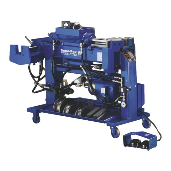
Model 1502-BA
shown with typical
tooling package.
Advertisement
Table of Contents


Need help?
Do you have a question about the 1000-BL and is the answer not in the manual?
Questions and answers