BendPak Blue Bullet 1302-BAS Operation And Service Manual
Tubing bender
Hide thumbs
Also See for Blue Bullet 1302-BAS:
- Operation and service manual (72 pages) ,
- Operation and service manual (60 pages) ,
- Operation and service manual (58 pages)
Table of Contents
Advertisement
MODELS:
BB ("Blue Bullet")
1302-BAS
Keep this operation manual near the
machine at all times. Make sure that ALL
USERS read this manual .
SHIPPING DAMAGE CLAIMS
When this equipment is shipped, title passes to the
purchaser upon receipt from the carrier. Consequently,
claims for material damaged in shipment must be made by
the purchaser against the transportation company at the
time shipment is received.
PLEASE READ THE ENTIRE CONTENTS OF THIS MANUAL PRIOR TO
INSTALLATION AND OPERATION. BY PROCEEDING YOU AGREE THAT YOU
FULLY UNDERSTAND AND COMPREHEND THE FULL CONTENTS OF THIS
MANUAL. FORWARD THIS MANUAL TO ALL OPERATORS. FAILURE TO
OPERATE THIS EQUIPMENT AS DIRECTED MAY CAUSE INJURY OR DEATH.
OPERATION AND SERVICE MANUAL
"America's Most Popular Tubing Bender"
BE SAFE
BendPak, Inc. benders are designed and built with safety
in mind. However, your overall safety can be increased by
proper training and thoughtful operation on the part of the
operator. DO NOT operate or repair this equipment without
reading this manual and the important safety instructions
shown inside.
REV. D - FEB. 2019
pn# 5900103
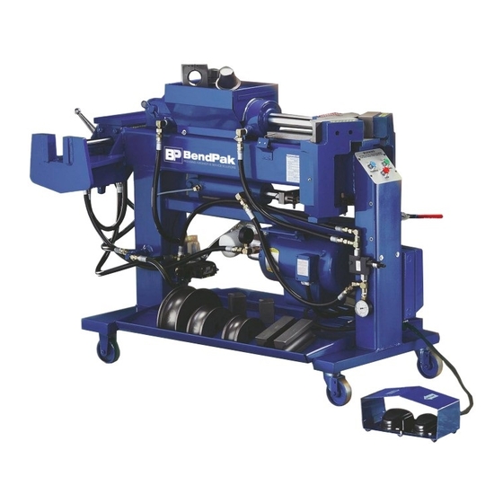
1302-BAS shown
1645 Lemonwood Dr.
Santa Paula, CA. 93060, USA
Toll Free 1-800-253-2363
Tel: 1-805-933-9970
www.bendpak.com
Advertisement
Table of Contents

Related Manuals for BendPak Blue Bullet 1302-BAS


Summary of Contents for BendPak Blue Bullet 1302-BAS
- Page 1 SHIPPING DAMAGE CLAIMS BE SAFE When this equipment is shipped, title passes to the BendPak, Inc. benders are designed and built with safety purchaser upon receipt from the carrier. Consequently, in mind. However, your overall safety can be increased by...
-
Page 2: Table Of Contents
TABLE OF CONTENTS Identification Data / Warranty ............................. 3 Specifications ................................4 Important Safety Instructions............................5 Definition Of Terms / Model Identification ........................6 Installing The Electrical Plug ............................7 Turning Your New Bender On ............................8 Introduction Of Tooling Identification .......................... 8 Segment Identification Chart ............................. 11 Typical End Finishing Illustrations .......................... -
Page 3: Identification Data / Warranty
YOUR NEW BENDER This instruction manual has been prepared especially for you. Your new bender is the product of over 30 years of continuous research, testing and development and is the most technically advanced bender on the market today. READ THIS ENTIRE MANUAL BEFORE OPERATION BEGINS. The manner in which you care for and maintain your bender will have a direct effect on it's overall performance and longevity. -
Page 4: Specifications
SPECIFICATIONS DESIGN FEATURES DESIGN FEATURES MODELS 1302-BAS MODELS 1000BL / 1000 BAS Bending Capacity ......Tubing from 1/2” OD - 3” OD Bending Capacity ......Tubing from 1/2” OD - 3” OD Maximum Capacity/Tube Thickness ..See Chart Below Maximum Capacity/Tube Thickness ..See Chart Below Maximum Bending Radius ....5”... -
Page 5: Important Safety Instructions
UPON DELIVERY 1. Carefully remove the crating and packing materials. 3. Check the voltage, phase and proper amperage requirements for the motor shown on the motor plate. 2. Inspect the bender for any signs of concealed Wiring should be performed by a certified electrician only. -
Page 6: Definition Of Terms / Model Identification
INTRODUCTION Your new bender is a “press-style” bender that is capable of bending, flaring and swaging tubing up to 3 inches in diameter. The thickness of the tubing plays an important part. (See previous chart for recommended tubing allowances.) The front of the bender is where all the bending is performed. -
Page 7: Installing The Electrical Plug
CONTROL FEATURES BL or BLUE-BULLET Models - A hydraulic control valve is located at the front of the machine at knee height that allows the operators to manually control the machine with their leg. A degree plate is mounted up front that shows proper bend depths. -
Page 8: Turning Your New Bender On
TURNING YOUR NEW few cycles due to air trapped in the lines. This is normal. The air will dissipate after use. Do not try to BENDER ON “crack” a line to help the air escape. 1. Plug the power cord into a receptacle closest to the 10. - Page 9 Half Shoe Three Quarter Shoe BACK SHOES - Back shoes, which are commonly referred to as wiper dies come in pairs and are used together with the radius dies during the bending process. CAUTION! These dies play an important part as their primary purpose All tooling described in this manual is heavy! is to form the outside radius of the bend.
- Page 10 END-FINISHING TOOLS - A variety of end finishing tools REDUCING TOOLS - Reducing tools are used for are available that perform different functions. Not every reducing or “shrinking” pipe ends to exact outside tool is included with your tooling package. If you are diameters.
-
Page 11: Segment Identification Chart
STANDARD SEGMENT SETS - These segment sets are used to make straight expansions on tubing ends and are found in all standard tooling packages. HSA-112 Arbor HSA-114 Arbor WARNING! 1. Always remove excess tooling from swager area before using internal expander. NOTE: 2. -
Page 12: Description Of Three-Button Control (Bas Models)
THREE-BUTTON DESCRIPTION OF CONTROL OPERATIONS CONTROLS: NEVER HOLD IN COLORED CONTROL BUTTONS! - “BAS” MODELS To properly operate the colored control buttons, quickly Read each of the following sections carefully before press and release. By holding the colored control buttons attempting any operation of this unit. - Page 13 OPERATING THE MANUAL USING THE “AUTO-STOP” DEPTH-OF-BEND FEATURE The “Auto-Stop” slide pointer is attached to the depth-of- KNEE CONTROL bend degree plate and stops the radius die at pre-set bend depths. The “Auto-Stop” feature works with either BULLET MODELS the GREEN automatic control button or the remote foot switches.
-
Page 14: Operating The Manual Knee Control (Bl / Bullet Models)
To use the three-button automatic controls, follow these simple instructions. 1. Position the “Auto-Stop” pointer at the desired depth of bend. 2. Position the tubing at the appropriate bend mark. 3. Check your “circle-of-swing” and prepare to begin bending. 4. Press the GREEN control button. 5. -
Page 15: Using The Program Cards
Sample screen shots of cards with specific bending instructions. Look up the make and model of the vehicle using the BENDING INSTRUCTIONS - Shows what radius die will Exhaust Pro Software to find the "card" or "record" be used in addition to other tooling such as half shoes and number. - Page 16 4. Using the program card, refer to the section marked NOTE: CENTER MARKS for the list of measurements in The weld seam on the tubing should be directly in line inches where the different bends will be made. Each with the ZERO mark at this time. (See figure 2-A) CENTER MARK is measured from the left end of the tubing.
- Page 17 Figure 2-B IMPORTANT NOTE: The ROTATION DIAL degree plate MUST NEVER be moved after bending has begun. ALWAYS be prepared to support the tubing as it is released from the dies to prevent it from hitting the ground. If the dial is accidentally moved during the bending process, re-position the dial so that the ZERO mark is located at the weld seam of the tubing, or return to the previous bend and...
-
Page 18: Pattern Bending
22. Review the SYMBOLS section of the card and Figure 3-C check for any special instructions. 23. On bend number four you will notice that a REVERSE USE HALF SHOE is again called for. Keep the ROTATION DIAL on the LEFT side for this bend. 24. - Page 19 ALWAYS USE THE NUMBERS CLOSEST TO THE CENTER OF THE ROTATION DIAL. THE OUTSIDE NUMBERS ARE FOR SPECIAL APPLICATIONS ONLY. Record the rotation degree as zero for your first PIPE ROTATION. 7. You are now ready to make your first bend. Place the first bend of the master pipe or wire flat on top of the back shoes.
-
Page 20: Blank Program Card
Figure 2-A NOTE: Repeat these steps for the remaining bends. After all bends are completed, make the necessary end finishing and take a measurement for the overall cut off length. Be sure to make all notations on the blank program card for later reference. USING A BLOCK OF WOOD Some bending cards or certain bending applications require the use of a BLOCK OF WOOD. -
Page 21: Stainless Tube Bending Procedure
BENDING STAINLESS Figure 3-B TUBING In order to get good results when bending stainless tubing, it is necessary to increase the back shoe pressure by adjusting the sequence valve similar to the procedure previously described. The recommended pressures are shown below. When using large diameter or light gauge tubing, more back shoe pressure is required. -
Page 22: Using The Standard Segment Expanders
USING THE STANDARD SEGMENT EXPANDERS Figure 1-A There are five standard segment sets included with your bender. Each segment set is designed to be used with a particular size tubing only. The appropriate sizes are shown below. Standard segment sets are used for making straight expansions. -
Page 23: Using The Ball-Joint Segment Expanders
Lift the valve handle up until the arbor extends and Depress the valve handle to form the ball on the end the segment set is released. of the tubing. Be careful not to distort the end of the tubing. (See figure 2-A) 10. -
Page 24: Using The Manifold Flange Segment Expanders
2. Place the tubing over the arbor and segment set, but 3. Position the tubing over the arbor and segment set DO NOT place the end of the tubing past the last until the tubing meets the shoulder. step on the segment set. (See figure 1-A) 4. -
Page 25: Using The Sted Expander Dies
MAKING STRAIGHT EXPANSIONS 7. After the tubing has been expanded, retract the die Follow these steps to produce straight expansions using by lifting up on the control handle. the STEP expander dies. (See chart on page 12 for typical end finishing illustrations.) 8. -
Page 26: Making Female Ball Expansions
4. Leave at least three inches of tubing extended Figure 3-A beyond the inside edge of the adapter collar. (See figure 2-B) Figure 2-B Slowly, move the tool forward until the desired ball is achieved. This procedure requires careful control. (See figure 1-B) Snug the collar back into the clamp blocks by gently Figure 1-B... -
Page 27: Making A Manifold Flange Using The Hpf-300 Tool
4. Leave at least three inches of tubing extended Figure 2-C beyond the inside edge of the adapter collar. (See figure 1-A) Figure 1-A Retract the die by lifting up on the control handle. Separate the collar from the tubing. Remove Snug the collar back into the clamp blocks by gently tooling and return to the storage area. - Page 28 CAUTION! 5. Snug the collar back into the clamp blocks by gently pushing back on the collar assembly. Pay careful attention when performing the following steps. KEEP HANDS CLEAR from all 6. Slowly, while depressing the valve handle down, pinch points. move the shaft forward until the tool enters the tubing.
-
Page 29: Making A Manifold Flange Using The Cft Tool
USING THE CFT TO MAKE A MANIFOLD FLANGE. 8. Retract the die by lifting up on the control handle. 9. Separate the collar from the tubing. Remove tooling IMPORTANT NOTE: and return to the storage area. When making a manifold flange, it is necessary to first install the pipe flange or clamp around the USING THE REDUCING TOOLS - Reducing tools are tube prior to finishing the ends. -
Page 30: Using The Doming Die To Finish Tailpipe Ends
8. Retract the die by lifting up on the control handle. 7. Slowly, move the tool forward until the desired finish (See figure 2-C) is achieved. (See figure 1-A) Figure 2-C Figure 1-A 9. Separate the collar from the tubing. Remove tooling and return to the storage area. -
Page 31: Maintenance Introduction
5. Snug the collar back into the clamp blocks by gently pushing back on the collar assembly. 6. Slowly, while depressing the valve handle down, move the shaft forward until the tool enters the tubing. Be sure that the tool is centered with the tubing. -
Page 32: Pressure Settings
NOTE: 5. If an adjustment is required, loosen the locking nut that secures the adjusting screw. Loose hoses and hydraulic components will not always show a visual sign of leakage, however they can cause 6. To increase the pressure, turn the adjusting screw aeration of the system by “sucking”... -
Page 33: Chain Adjusting Procedure
If the return pressure needs adjusting, proceed as follows. To check and adjust the system pressure, proceed as follows. 1. Turn the machine on. 1. Turn the machine on. 2. Place a radius die and set of back shoes in position. 2. -
Page 34: Aligning The Guide Plate
LEVELING THE GUIDE PLATE WITH THE BACK GATES The back gates and guide plate have been precisely leveled at the factory and should seldom require adjustment. If however, the guide plate becomes un-level with the back gates, the bending dies will become misaligned and cause the tubing to wrinkle. -
Page 35: Barrel Bushing Maintenance
6. It will not be necessary to loosen the rear most bolt Figure 2-C on the guide plate for this service. 7. Using a pry bar, elevate the front of the guide plate. (See figure 2-A) 2. Remove the barrel shaft nut located below the left side gate assembly. -
Page 36: Aligning The Swager Box Cylinder
Visually check bronze bushings for excessive wear. Hold the tubing securely making sure that the HAC-300 is square within the clamp blocks. Replace bushings if inside diameter is greater than 2.005” or more. (See figure 3-A) Advance the tool forward until it just makes contact with the tubing. -
Page 37: Pusher Block Maintenance
Check to see if the pusher block is square to the guide Figure 1-A plate as illustrated below. 12. Shim the swager cylinder as necessary by inserting shim stock between the cylinder end block and the swager box until proper alignment is achieved. (See figure 1-B) Figure 1-B If the pusher block is excessively worn or out of square,... -
Page 38: Calibrating The Depth-Of-Bend Plate Manual Models
CALIBRATING THE AUTOMATIC Remove the pusher block by sliding it to the rear end DEPTH-OF-BEND SWITCH / “BAS” MODELS then off of the guide plate Carefully re-install the new pusher block (it should be Before attempting the following, first calibrate the depth- tight) by reversing these steps. -
Page 39: Operating The Machine Manually Using The Solenoid Valve
Loosen the set screw on the adjustable trip arm The manual buttons control the top cylinder as follows; located directly underneath the depth-of bend To advance the radius die - Press the right button plate and adjust so that it just activates the inward using an insulated tool or non-conducting rod. -
Page 40: Checking The Micro Switches (Automatic Models)
ELECTRICAL REPAIR To tell if the micro switch is good, remove it from the machine and use an ohmmeter to check the circuits as follows: WARNING! WITH THE SWITCH IN THE NEUTRAL POSITION - Electrical equipment should be serviced by Place one of the prongs from your ohmmeter on the certified electrician’s only. -
Page 41: Motor Lead Connections
MOTOR CONNECTIONS CAUTION! All “BAS” models wired for more than For motor lead connections, refer to the charts below. In 220 volts are factory equipped with a transformer addition, to the motor lead wires it is necessary to connect to reduce the incoming voltage to the circuit board the green ground wire. -
Page 42: Manual Electric Starter
ELECTRIC FOOT SWITCH RECOMMENDED MAINTENANCE On a regular basis, inspect the electric foot switch Use a small file to remove any small nicks or scratches assembly for wear or damage. Inspect the entire length on the chrome cylinder rods. of the connecting cord for wear or deterioration. ALWAYS keep the chrome cylinder rods clean. -
Page 43: Trouble Shooting Procedures
TROUBLESHOOTlNG Introduction; The troubleshooting procedures shown on the following pages contain certain systems and/or conditions, possible causes and the corrective actions required. The chart gives the easiest corrective action first, then proceeds with more difficult procedures. Be certain that the person(s) working on the machine have the ability to do the service. Only certified electricians should work on electrical components. - Page 44 SYMPTOM / CONDITION POSSIBLE CAUSE CORRECTIVE ACTION BAS models - The bending ram The rear limit switch is malfunctioning. Check wire connections on the rear limit continues retracting even after the rear switch. Refer to diagram on page 50. limit switch is activated. Pressure builds Check micro switch with ohmmeter as up on the sequence valve gauge.
-
Page 45: Bending Problems
BENDING PROBLEMS Bending complications can be usually attributed to tubing thickness, tubing quality or improper radius selection. The bigger the tubing diameter, the bigger the radius and wall thickness should be. See the chart below for minimum tubing thickness and proper radius selection. Tubing Diameter Minimum Tubing Thickness Minimum Tubing Thickness... -
Page 46: Electrical Wiring Diagrams (Models Bas)
46 Bender Operation Manual... -
Page 47: Die Package For Blue Bullet
B-1 Tooling Package BENDING DIES PIPE COLLARS QTY. PART NO. TOOLING DESCRIPTION QTY. PART NO. TOOLING DESCRIPTION 5R-212 5 " Radius Die / 2-1/2" HAC-212 2-1/2" Pipe Collar 5R-214 5 " Radius Die / 2-1/4" HAC-214 2-1/4" Pipe Collar 5R-200 5 "... -
Page 48: Die Package For Blue Bullet
B2 Deluxe Tooling Package BENDING DIES PIPE COLLARS QTY. PART NO. TOOLING DESCRIPTION QTY. PART NO. TOOLING DESCRIPTION 5R-212 5 " Radius Die / 2-1/2" HAC-212 2-1/2" Pipe Collar 5R-214 5 " Radius Die / 2-1/4" HAC-214 2-1/4" Pipe Collar 5R-200 5 "... -
Page 49: Economy 202 Die Package
202 Tooling Package BENDING DIES PIPE COLLARS QTY. PART NO. TOOLING DESCRIPTION QTY. PART NO. TOOLING DESCRIPTION 5R-212 5 " Radius Die / 2-1/2" HAC-212 2-1/2" Pipe Collar 5R-214 5 " Radius Die / 2-1/4" HAC-214 2-1/4" Pipe Collar 5R-200 5 "... -
Page 50: Deluxe 302 Die Package
302 Deluxe Tooling Package BENDING DIES PIPE COLLARS QTY. PART NO. TOOLING DESCRIPTION QTY. PART NO. TOOLING DESCRIPTION 5R-212 5 " Radius Die / 2-1/2" HAC-212 2-1/2" Pipe Collar 5R-214 5 " Radius Die / 2-1/4" HAC-214 2-1/4" Pipe Collar 5R-200 5 "... -
Page 51: Parts Breakdowns
Bender Operation Manual 51... - Page 52 52 Bender Operation Manual...
- Page 53 Bender Operation Manual 53...
- Page 54 54 Bender Operation Manual...
- Page 55 Bender Operation Manual 55...
- Page 56 56 Bender Operation Manual...
- Page 57 Bender Operation Manual 57...
- Page 58 58 Bender Operation Manual...
- Page 59 Bender Operation Manual 59...
- Page 60 60 Bender Operation Manual...
- Page 61 Bender Operation Manual 61...
- Page 62 62 Bender Operation Manual...
- Page 63 Bender Operation Manual 63...
- Page 64 64 Bender Operation Manual...
- Page 65 58 Rockwell. No cast or ductile (brittle) iron is used for any of our tooling. All BendPak benders are built with 3” bending capacity so you can order three inch dies when you need them. No other manufacturer uses our exclusive step-cut process for the die rails that actually helps contain the larger size tubing better and gives you a more uniform bend.
- Page 66 58 Rockwell. No cast or ductile (brittle) iron is used for any of our tooling. All BendPak benders are built with 3” bending capacity so you can order three inch dies when you need them. No other manufacturer uses our exclusive step-cut process for the die rails that actually helps contain the larger size tubing better and gives you a more uniform bend.
-
Page 67: Notes
Notes: _____________________________________________________ _____________________________________________________ _____________________________________________________ _____________________________________________________ _____________________________________________________ _____________________________________________________ _____________________________________________________ _____________________________________________________ _____________________________________________________ _____________________________________________________ _____________________________________________________ _____________________________________________________ _____________________________________________________ _____________________________________________________ _____________________________________________________ _____________________________________________________ Bender Operation Manual 67... - Page 68 For Parts Or Service Contact: BendPak Inc. / Ranger Products 1645 Lemonwood Dr. Santa Paula, CA. 93060 Tel: 1-805-933-9970 Toll Free: 1-800-253-2363 Fax: 1-805-933-9160 www.bendpak.com www.rangerproducts.com pn#5900103...
Need help?
Do you have a question about the Blue Bullet 1302-BAS and is the answer not in the manual?
Questions and answers