Advertisement
Quick Links
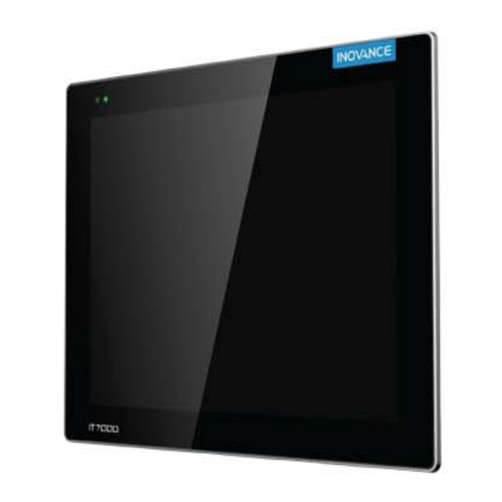
IT7150E HMI
User Guide
Thank for purchasing the IT7000 series human machine interface (hereinafter referred to as HMI) developed
and manufactured by Inovance. The IT7150E HMI, which is developed based on Linux system, adopts Android-
style display featuring high resolution and high-performance processor featuring quick data processing and high
response speed, providing users with excellent interactive experience.
The IT7150E HMI supports: 1) customized styles, VNC remote desktop, vector icons, and script programming;
2) connection to PC through USB or Ethernet; 3) monitoring on PLC and PLC program upload/download for easy
commissioning; 4) Modbus protocol and efficient communication with PLC; and 5) update of the HMI firmware,
interface program, and recipe data through U-disk. When it is used with an Inovance PLC, you can update the
PLC program for easy download of programs in the manufacturing devices on site. To facilitate HMI program and
system commissioning, online simulation and offline simulation are available in IT7150E HMIs.
Min
This user guide describes the specifications, features, and usage of IT7150E HMIs. Read through this user
guide before use to ensure a good understanding of product features and a safe use. For details on use of user
program development environment and user program design methods, see the help file in the software tool
"InoTouchPad". The latest version of InoTouchPad is released on www.inovance.com.
Safety Instructions
Safety Precautions
1) Read through the safety instructions before installing, operating, and servicing the product.
2) To ensure personal and equipment safety, observe the notes indicated on the product labels and all the safety
instructions in the user guide.
3) The "CAUTION", "WARNING", and "DANGER" signs are only supplements to the safety instructions.
4) Operate the product only in environments compliant with design specifications. Failure to comply may result in
faults. Damage caused by improper usage is not covered by warranty.
5) Inovance shall take no responsibility of any personal injuries or property damages caused by improper usage.
Safety Levels and Definitions
Indicates that failure to comply with the notice will result in severe personal injuries or even death.
DANGER
Indicates that failure to comply with the notice may result in severe personal injuries or even death.
WARNING
Indicates that failure to comply with the notice may result in minor or moderate personal injury or
CAUTION
damage to the equipment.
Keep this user guide in a proper place for future reference. Deliver this user guide to the end user.
Design
DANGER
◆ The interlock circuit and other circuits such as emergency stop, regular protection, and forward/reverse rotation
circuits must be set independent of the product. Devices used to prevent equipment damage, such as up/down
limit switches and reciprocating motion limit switches, must also be set independent of the product.
◆ A fault protection circuit must be set independent of the product to prevent unexpected mechanical movement
caused by, for example, errors in the non-detectable I/O control area.
◆ A user program must be designed to ensure safety of the user system in case of faults, including the display,
control, communication, and power supply faults.
◆ Measures must be taken to avoid malfunction caused by communication faults between the product and the
host controller, preventing personal injuries and equipment damage.
◆ Do not bring live parts into contact with the metal enclosure of the product.
CAUTION
二维码
综合手册
◆ Do not create switches that may result in personal injury or equipment damage on the touch screen. Use
independent switches for critical operations. Failure to comply may result in accidents caused by wrong outputs
A00
or faults.
资料编码 19010306
◆ Do not create switches used to control equipment safety operations on the touch screen, such as the emergency
stop switch. Use independent hardware switches for safety-related operations. Failure to comply may result in
severe personal injury or equipment damage.
◆ Do not use the product to alarm critical warnings that may cause severe personal injury, equipment damage
or system stop. Use independent hardware/mechanical interlocks to design mechanisms used to alarm critical
warnings and devices used to control/trigger such mechanisms.
DANGER
◆ Install the product indoors and ensure the operating environment complies with the requirements described in
the user guide.
◆ Install the product in a place free from strong magnetic field, direct sunlight, high temperature, inflammable
gas, vapor, and dust. Failure to comply will result in the risk of explosion.
◆ Operate the product only in environments without drastic temperature changes or high humidity. Failure to
comply may result in damage to the product due to formation of condensated water inside the product.
◆ Ensure all the cable connectors are connected securely to the product. Loose connections may result in I/O
signal errors.
CAUTION
◆ Install the product in environments with temperatures within the recommended storage temperature range.
Failure to comply may result in display faults of the LCD.
DANGER
◆ Cut off all the power supplies before installation, wiring, and plug-in/plug-out of cable connectors. Failure to
comply will cause electric shock or circuit damage.
*19011415A00*
◆ Wire the DC power supply to the dedicated terminals as described in the user guide.
◆ Avoid metal chippings or cable terminals from falling into the product during screw hole machining and wiring.
This is to prevent faults, component damage, and fire accidents.
19011415
A00
◆ Perform meticulous inspections after wiring to ensure the operating voltage and terminal positions are correct.
1
Failure to comply may result in the risk of fire or accident.
CAUTION
◆ To avoid electric shock, cut off the power supply before connecting the power supply of the product.
◆ The product is powered up by a 24 VDC power supply. Power supplies outside ±20% of 24 VDC will result in
severe damage to the product. Therefore, check whether the DC power supply provided by the switched-mode
power supply is stable at a regular interval.
CAUTION
◆ Touch the HMI panel with hands or professional tools (such as a stylus) only during use. Inovance assumes no
responsibility for panel damage caused by excessive external force.
◆ The lithium battery may contain elements that are harmful to personal health and the environment. Dispose of
the battery according to local laws and regulations.
Safety recommendations
◆ In positions where the operator touches the mechanical parts directly, such as positions for loading and
unloading machinery tools, or positions where the machine operates automatically, manually-operated devices
or other backup measures used to start or stop system operations must be available on site. Such devices or
backup measures must be set independent of the programmable controller.
◆ In cases where the program needs to be modified during system operation, use an encryption lock or other
protective measures to allow the program to be modified by authorized operators only.
CAUTION
◆ Dispose of the product as an industrial waste.
1 Product Information
1.1 Designation Rules
1.2 Basic Parameters
Model
IT7150E
Inovance IT7000 series 15" touch screen
Item
Specifications
Display dimension
15"
Resolution
1024x768
Brightness (cd/m
)
300
2
Display color
24-bit true color
Backlight source
LED
Backlight service life 50000 hrs
Cut-out dimensions 352x279
Enclosure color
Silver
Installation
Wiring
Operation and Maintenance
Disposal
Description
Item
Specifications
CPU
Cortex A8 (1 GHz)
DRAM
256 MB DDR3
Flash
256 MB
RTC
✓
Serial port
COM1 (RS422/RS485); COM2 (RS232); COM3 (RS485)
One 10 M/100 M adaptive RJ45 Ethernet port with
Ethernet port
LED indicator
Cable length within 100 m, CAT5/CAT5E
Mini USB type-B port One USB type-B port
One USB type-A port
USB type-A port
Note: The USB type-A port provides current within
200 mA only.
2
Model
Front housing:
aluminum alloy;
Enclosure material
SD card interface
Rear cover:
sheet metal
Operating
0℃ to 50℃
DI/DO
temperature
Storage temperature -20℃ to +70℃
Input voltage
10%–90% RH (no
Working humidity
Rated current
condensation)
Cooling mode
Natural ventilation IP rating of the panel Front panel: IP65; Rear cover: IP20
◆ The design service life of the built-in button battery is five years. The actual service life of the
battery varies with the operating conditions (temperature and humidify).
2 Mechanical Design Reference
NOTE
2.1 Installation Environment
1) The HMI is designed to operate in a temperature range between 0℃ to 50℃ (32℉ to 122℉), exceeding of which
may cause component damage, malfunction, or function degradation. For use in special environments, contact
the supplier.
2) Do not install the HMI in environments suffering from strong mechanical vibration.
3) Install the HMI into a cabinet with a depth of over 105 mm and reserve a surrounding clearance of at least 25 mm.
4) Install the HMI away from cables and devices generating strong interference, such as AC power supply cables,
PLC output modules, AC drives, and relays. Use shielded cables for I/Os and ground the shielded cable properly.
5) The front panel of the HMI complies with IP65 requirements. The cabinet in which the HMI is installed must also
comply with IP65 requirements, which means liquid sprayed to the surface of the cabinet will not penetrate into
the cabinet.
2.2 Mounting Dimensions
Outline Dimensions
Display
Model
Dimension
Width x Height x Depth (mm)
IT7150E
15"
367.8 x 294.8 x 53
2.3 Mounting Mode
See the following steps for through-hole mounting:
1)
Put the HMI into the pre-drilled mounting holes in
the cabinet panel.
2)
Snap the eight metal clips (delivered by default)
from the back of the cabinet panel into the
eight mounting holes on both sides of the HMI
enclosure (step ① in the figure).
3)
Tighten the mounting screws one by one until the
HMI is secured to the cabinet panel (step ② in the
figure). The recommended tightening torque is
6.0±0.5 kgf/cm (a tightening torque within this
range achieves the waterproof purpose and
avoids deformation).
CAUTION
To comply with IP65 sealing specifications, ensure all the mounting screws delivered are used and the
curvature of the mounting panel is no greater than 0.010° after installation.
Do not apply excessive force when tightening the mounting screws. If you have any question, contact the
DANGER
supplier.
3 Electrical Design reference
3.1 Terminal Descriptions
8
7
6
5
4
3
2
1
11
12
Side view
侧视图
No.
Name
Function
24 VDC power input ports of HMI, which are
Power
+24V and GND
1
supply
(The power supply terminal used to connect
ports
power supply ports is delivered by default.)
3
Description
One Micro SD card interface
Micro SD card supported, push-push type SD card
slot
8 DIs/4 DOs (reserved for customized needs)
8-channel DI detection, 4-channel transistor output
24 VDC±20%
800 mA
Recommended
Through-hole Mounting
Cut-out Dimensions (mm)
Dimensions (W x H) (mm)
W+2
H+2
350x277
352
279
No.
Name
Function
Ethernet communication port
Ethernet
7
(RJ45) used to access a PC or PLC
port
with LAN port
Advertisement

Related Manuals for Inovance IT7150E

Summary of Contents for Inovance IT7150E
- Page 1 4) Modbus protocol and efficient communication with PLC; and 5) update of the HMI firmware, ◆ Touch the HMI panel with hands or professional tools (such as a stylus) only during use. Inovance assumes no interface program, and recipe data through U-disk. When it is used with an Inovance PLC, you can update the responsibility for panel damage caused by excessive external force.
- Page 2 Ground Inovance provides preformed communication cable options (model: IT5-H2U-CAB*, ordering No.: 15041140) for DB9 1) Inovance provides an 18-month free warranty to the equipment itself from the date of manufacturing for the female. failure or damage under normal use conditions.
Need help?
Do you have a question about the IT7150E and is the answer not in the manual?
Questions and answers